35
NOTICE
Use suitable objects such as wooden
blocks to secure the B500/B500-S power wheelchair against sliding or tipping. The drive wheels must
rotate freely.
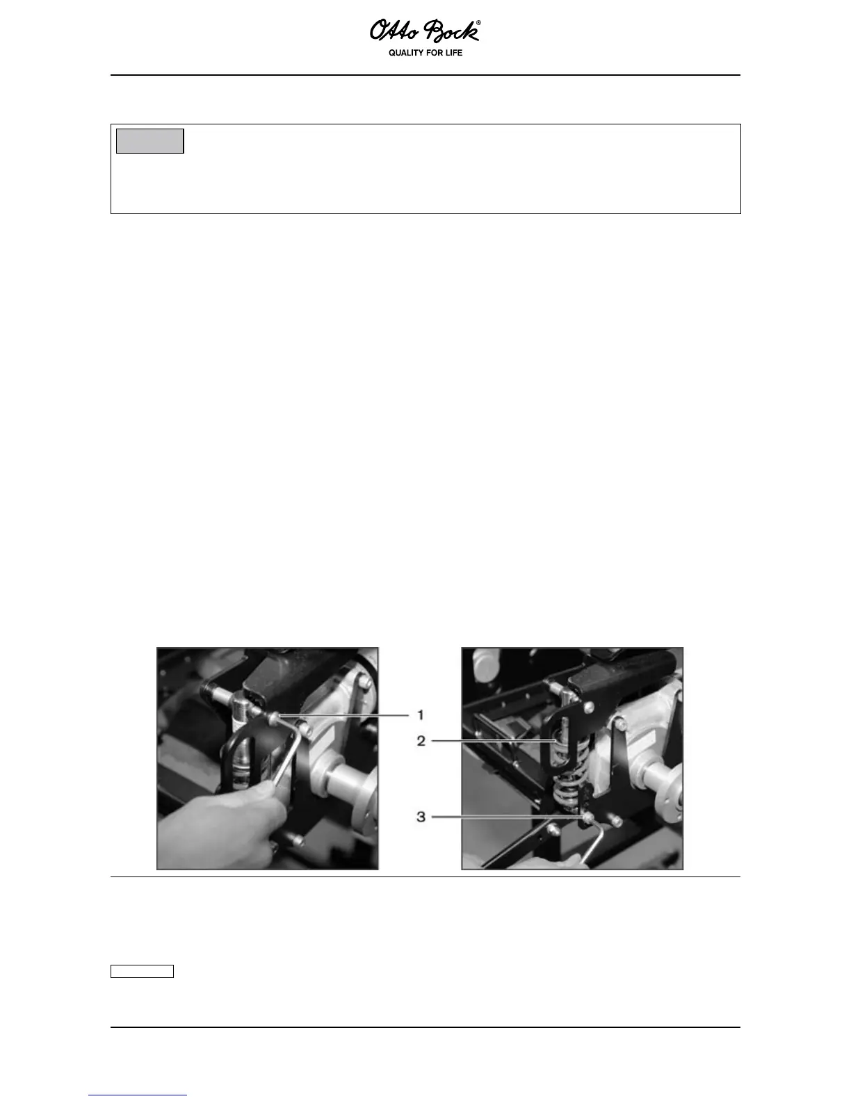
The drive wheel springs are attached at two points: At the top of the drive unit sustainer and on
the oscillating crank.
❒ Remove the drive wheel (see Section 6.7.3).
❒ Allen wrench, size 5
❒ Allen wrench, size 6
❒ Open-end or combination wrench, size 13
1. Loosen both Allen head screws holding the drive wheel spring and remove the drive wheel
spring.
2. Install a new drive wheel spring if required, or change the coefcient (turn the upper plate up
or down by hand):
– Turn to the left: Greater spring tension.
– Turn to the right: Less spring tension.
Properly reassemble all components upon completion of the work.
1 Upper screw connection
2 Plate to change the coefficient
3 Lower screw connection
Make sure that both springs are adjusted equally!
Factory pre-setting is 60 mm from the spindle to the spring plate.