88
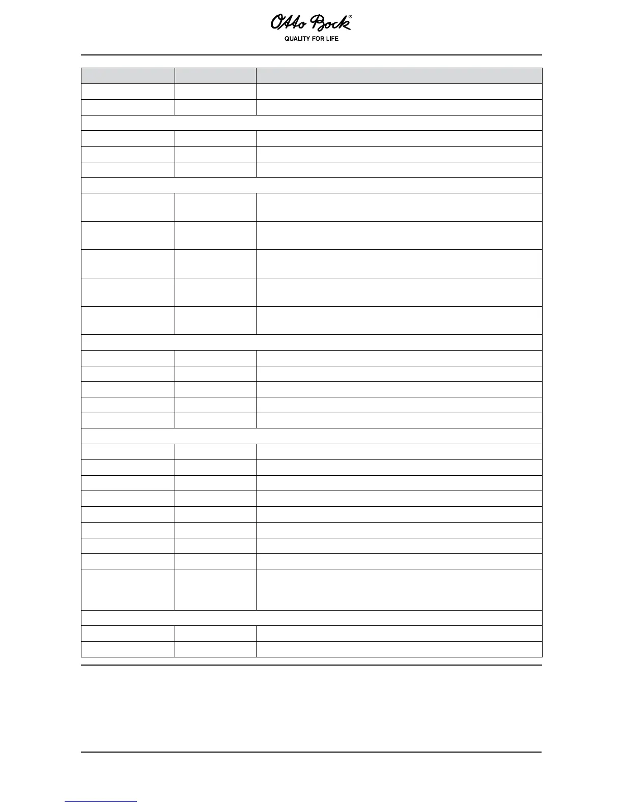
Headlight Button On/Off Status of the headlight button.
Charger Button On/Off Status of the Inhibit input.
Actuator 1 Voltage -24 – +24 V Voltage on actuator motor 1.
Actuator 2 Voltage -24 – +24 V Voltage on actuator motor 2.
Actuator Current -12 – +12 A Current on actuator motors.
Right Lamp
Voltage
0 – 24 V Voltage on the right-hand direction indicator lights.
Left Lamp
Voltage
0 – 24 V Voltage on the left-hand direction indicator lights.
Turn Signal
Current
0 – 6 A Current on the direction indicator lights.
Headlights
Voltage
0 – 24 V Voltage on the headlights.
Headlights
Current
0 – 6 A Current on the headlights.
Input 1 0 – 5 V Voltage on Multi-Function Input 1.
Input 2 On/Off Status of Multi-Function Input 2.
Input 3 On/Off Status of Multi-Function Input 3.
M1 Bridge Temp -40 – +150 °C Temperature of the power module for drive motor 1.
M2 Bridge Temp -40 – +150 °C Temperature of the power module for drive motor 2.
M1 Current -75 – +75 A Current on drive motor 1.
M2 Current -75 – +75 A Current on drive motor 2.
M1 Voltage -28 – +28 V Voltage on drive motor 1.
M2 Voltage -28 – +28 V Voltage on drive motor 2.
M1 PWM -100 – +100 % PWM on drive motor 1.
M2 PWM -100 – +100 % PWM on drive motor 2.
M1 Brake On/Off Status of the EM brake on drive motor 1.
M2 Brake On/Off Status of the EM brake on drive motor 2.
System
Resistance
0 –600 mΩ
System resistance as measured by the Powerbase on terminals
M1 and M2. This variable only supplies an accurate value if it
was measured with the Motor Test Mode parameter set to On.
Battery Voltage 0 – 38 V Battery voltage.
BDI % 0 – 100 % Battery capacity estimated by the Powerbase.
7.4 Hand Programming Device
The hand programing device allows the impulse controls to be programmed, examined and