61
(Option, B500-S Only)
When mounting a seat tilt, front anti-tipper wheels must be additionally mounted on B500-S (see Sec-
tion 6.17).
The B500-S can be equipped of a lift seat (up to 130 kg). The lift seat is delivered as a preas-
sembled unit (lift seat; combination lift seat / seat tilt).
❒ Remove the old seat including the seat plate and seat frame. Refer to Section 6.10.
❒ Allen wrench, size 5 mm
❒ Ring or open-end wrench, size 13
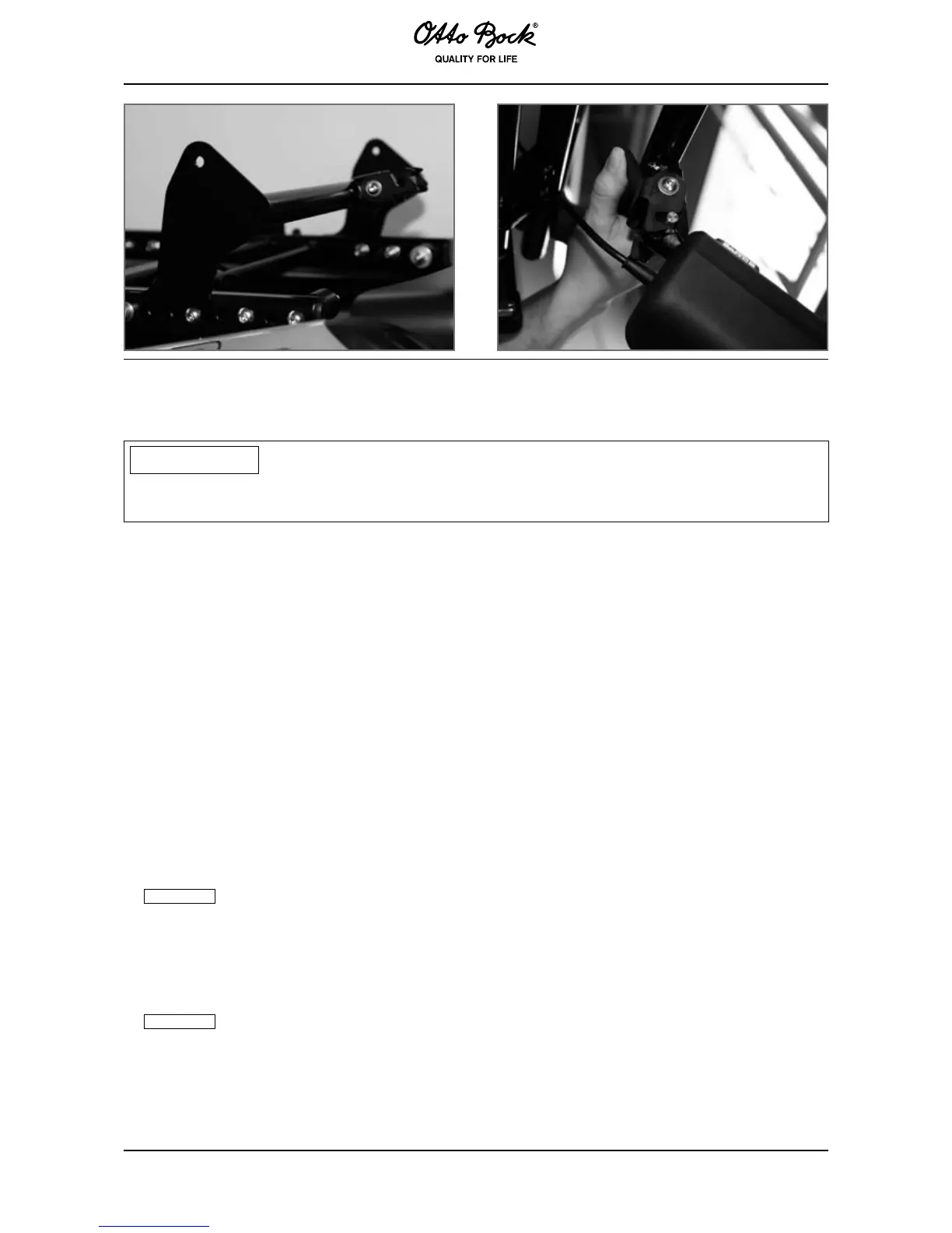
1. Install the frame of the seat tilt installation unit with supplied seat brackets (Figure 56-2: Front
seat brackets, Figure 56-3: Rear seat brackets) on the wheelchair frame.
2. Fasten the additional cables to the frame with cable ties to prevent them from extending into
the adjustment range.
The cabling is routed from the opening of the top expansion bellows plate along
the cable track installed on the right and left (Figure 56-4) to the seat module or controller.
Ensure the cable length is sufcient when the back angle adjustment option is activated and
that the cables cannot be crushed.
3. Set the magnetic pin – micro-switch gap.
A micro-switch activated by a magnetic pin (Figure 56-5) is located near the front of
the lift seat. It reduces the driving speed as soon as the lift seat moves from the lower home
position. The gap between the micro-switch and magnetic pin must not be more than 1 mm.
It is adjusted by turning the set screw on the magnetic pin.
4. Connect the additional cable to the actuator.