10.1 Overview of High-speed Counter Function
10-3
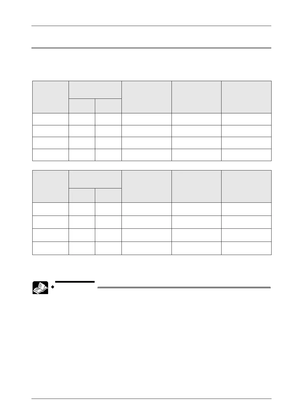
10.1.3 Areas Used For High-speed Counter Function
The usable combinations vary according to the unit type.
List of used areas
FP0H mode
Channel no.
Input no.
Control flag
Elapsed value
area
Target value area
Single-
phase
2-phase
CH0 X0 X0, X1 R9110
DT90300
DT90302
CH1 X1 - R9111
DT90302
DT90303
DT90306
DT90307
CH2 X3 X3, X4 R9112
CH3 X4 - R9113
FPΣ mode
Channel no.
Input no.
Control flag
Elapsed value
area
Target value area
Single-
2-phase
CH0 X0 X0, X1 R903A
CH1 X1 - R903B
CH2 X3 X3, X4 R903C
CH3 X4 - R903D
DT90204
DT90206
(Note 1): Functions, channel numbers and I/O numbers used are set in the tool software.
(Note 2): I/O numbers used for each function should be allocated so that they do not overlap. Refer to
"1.2Restrictions on Combinations and Functions".
• For details of the FPΣ mode, refer to "11. FPΣ Mode".