1.1 Functions of Unit
1-3
1.1.2 Compatibility Function with FPΣ
"FP0H mode" or "FPΣ mode" can be selected to retain compatibility with FPΣ. Usable
functions and performances vary according to each mode.
Each mode is selected in the system register no. 3 by the tool software.
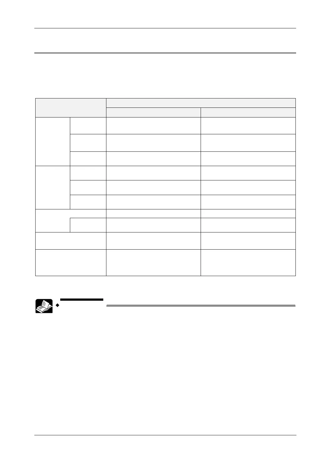
Comparison of functions and performances
Item
FP0H mode (Default)
FP
mode
High-speed
counter
Single-
phase
Max. 4 channels (CH0-3)
Max. 100 kHz×4
Max. 4 channels (CH0-3)
Max. 100 kHz×4
2-phase
Max. 2 channels (CH0, CH2)
Max. 50kHz×2
Max. 2 channels (CH0, CH2)
Max. 50kHz×2
I/O
allocation
Independent from pulse/PWM output. Shared with pulse/PWM output.
Pulse
output
Independent
Max. 4 channels (CH0-3)
Max. 100 kHz
Max. 2 channels (CH0, CH2),
Max. 100 kHz
Interpolation
Max. 2 channels (CH0, CH2)
Max. 100 kHz (Composite speed)
Max. 1 channel (CH0)
Max. 100 kHz (Composite speed)
I/O
allocation
Independent from high-speed counter
input.
Shared with high-speed counter input.
PWM output
Max. 4 points (CH0-3) Max. 2 points (CH0, CH2)
I/O
allocation
Independent from high-speed counter
input.
Shared with high-speed counter input.
Pulse output function Table setting mode
FPΣ compatible instruction mode
FPΣ compatible instruction mode
Explanation of each mode
Default setting for FP0H project.
There is no restriction on each
function.
Select when using FPΣ programs.
The performances of some functions
and I/O allocation are the same as
those of FPΣ.
(Note 1): Functions, channel numbers and I/O numbers used are set in the tool software.
(Note 2): I/O numbers used for each function should be allocated so that they do not overlap.
For details of the FPΣ mode, refer to “11. FPΣ Mode”.