Settings of Control Unit
4-2
4.1 Confirming I/O Allocation
4.1.1 When Using Pulse Output Table Setting Mode
• The home input signal and positioning completion signal is allocated to I/O signals.
• The pulse output table setting mode can be used only in the FP0H mode.
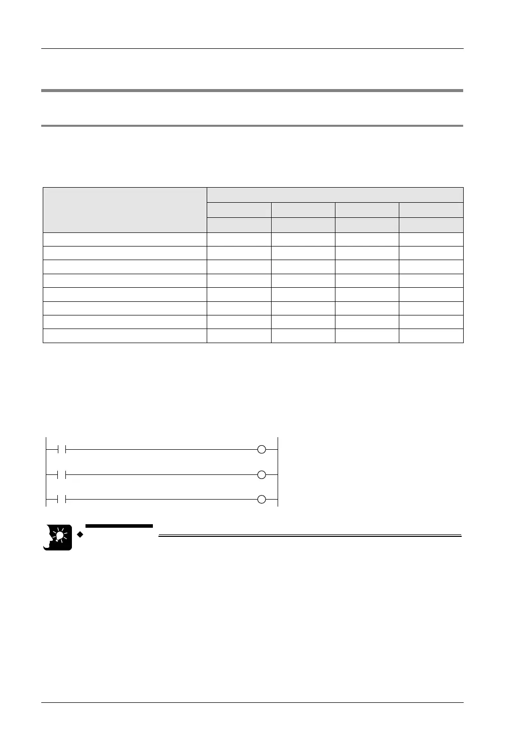
Allocation of I/O signals (Input)
Signal name
I/O number
Axis 1 Axis 2 Axis 3 Axis 4
CH0 CH1 CH2 CH3
J-point control positioning start input
X0 X1 X3 X4
Home input (Note1)
X2 X5 X6 X7
Near home input (Note 1) (Note 2) (Y850) (Y851) (Y852) (Y853)
Over limit input (+) (Note 2) (Y860) (Y862) (Y864) (Y866)
Over limit input (-) (Note 2)
(Y861) (Y863) (Y865) (Y867)
BUSY
X808 X809 X80A X80B
X810 X811 X812 X813
Home return done
X828 X829 X82A X82B
(Note 1): Even when setting the linear interpolation, the interpolation operation is not performed for the home return.
Execute the operation for X axes and Y axes separately.
(Note 2): The near home input, over limit input (+) and over limit input (-) will be valid when an arbitrary input is
allocated and the output relay indicated in the above table turns ON.
Sample program
The following sample shows the program when the near home input, over limit input (+) and
over limit input (-) are allocated to XA to XC.
• When selecting the table setting mode, the control active flags (R911C to
R911F) are not activated. Confirm that other instructions for the table
setting mode (F380 to F383) are not activated using the above BUSY flags
(X808 to X80B), and execute each instruction.