12.2 Allocation of Memory Areas
12-7
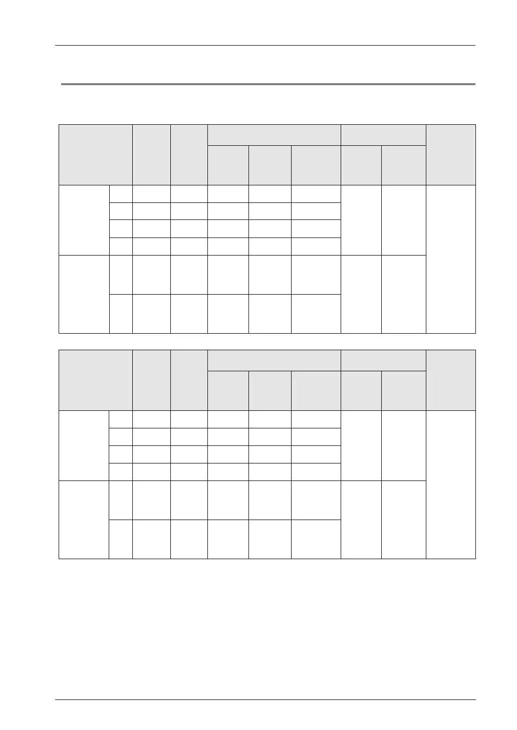
12.2.4 When Using High-speed Counter Function
Control unit
FP0H mode
Channel no.
Count
input
Hard-
ware
reset
input
Memory area used
Performance
Related
instruct-
tions
Control
flag
Elapsed
value
area
Target
value area
Min.
input
pulse
Max.
counting
speed
[Single-
phase]
Addition
input
Subtraction
input
CH0
X0 X2 R9110
High-
speed
input
5 μs
100kHz
F0
(MV)
F1
(DMV)
F165
(CAM0)
F166
(HC1S)
F167
(HC1R)
CH1
X1 X2 R9111
CH2
X3 X5 R9112
CH3
X4 X5 R9113
[2-phase
input]
Phase
difference
input
Individual
input
Direction
distinction
CH0
X0
X1
X2 R9110
DT90300
DT90301
DT90302
DT90303
High-
speed
input
10 μs
50 kHz
CH2
X3
X4
X5 R9112
DT90308
DT90309
DT90310
DT90311
FPΣ mode
Channel no.
Count
input
Hard-
ware
reset
input
Memory area used
Performance
Specifications
Related
instruct-
tions
Control
flag
Elapsed
value
area
Target
value area
Min.
input
pulse
Max.
counting
speed
[Single-
phase]
Addition
input
Subtraction
input
CH0
X0 X2 R903A
High-
speed
input
5 μs
100kHz
F0
(MV)
F1
(DMV)
F165
(CAM0)
F166
(HC1S)
F167
(HC1R)
CH1
X1 X2 R903B
CH2
X3 X5 R903C
CH3
X4 X5 R903D
[2-phase
input]
Phase
difference
input
Individual
input
Direction
distinction
CH0
X0
X1
X2 R903A
DT90044
DT90045
DT90046
DT90047
High-
speed
input
10 μs
50 kHz
CH2
X3
X4
X5 R903C
DT90200
DT90201
DT90202
DT90203
(Note 1): When the reset input settings of reset input for the single-phase input overlap at CH0 and CH1 or CH2 and
CH3, the setting of CH0 or CH2 has priority.
(Note 2) Only F1 (DMV) instruction can perform the reading and writing of elapsed value area.
Maximum counting speed
These values are available only when the conditions of each item (such as counting method
or channels) are executed. These values are available when the high-speed counter match
ON (F166) instruction, high-speed counter match OFF (F167) instruction, pulse output
function or other interrupt controls are not performed.