258
Setting Inspection Conditions
Optional Settings
1.
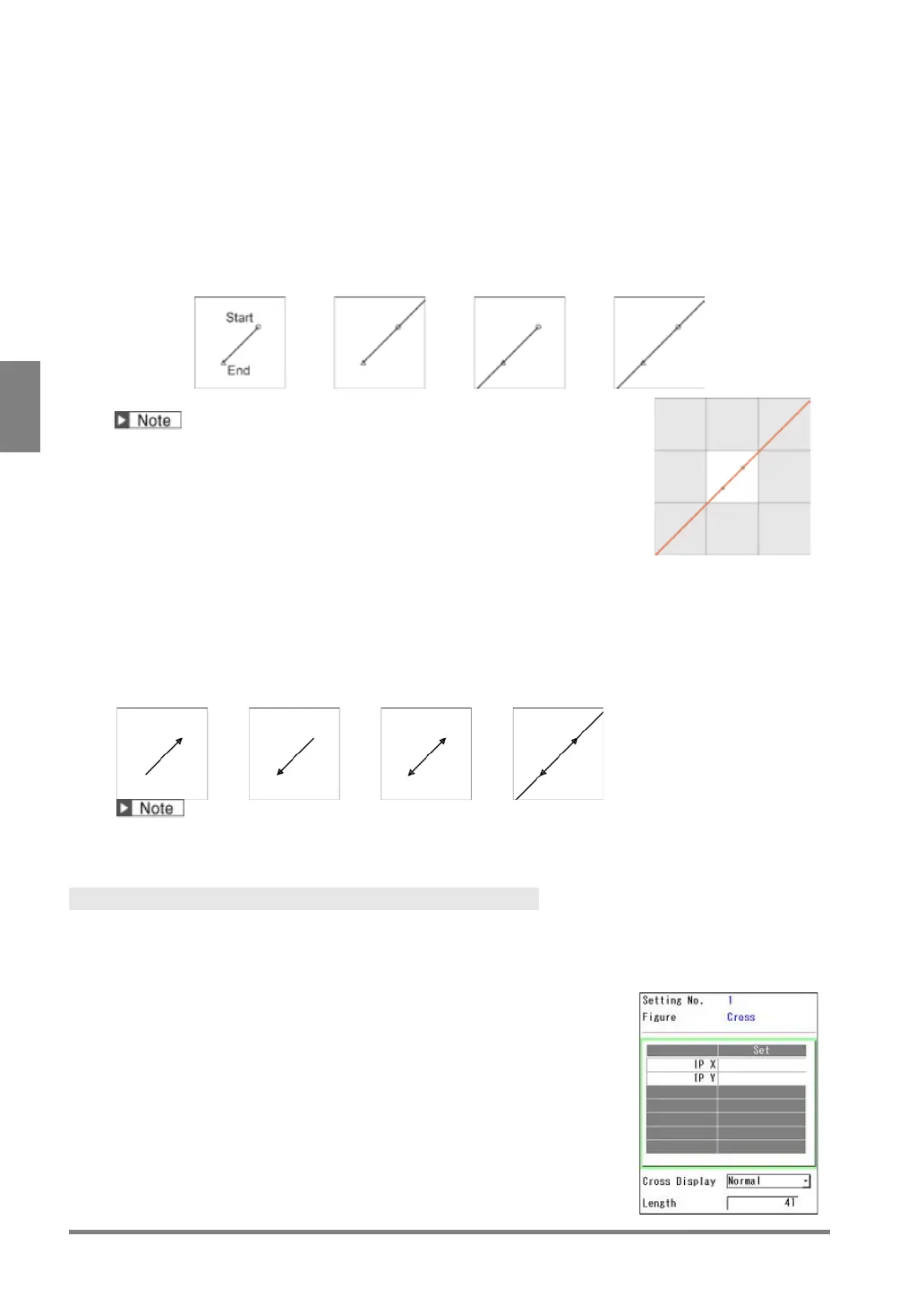
Select "Line Display".
Select the type of the line from the following four types.
the start and end
points.
the end point and the
edge of the screen in the
the start point and the
edge of the screen in the
the both edges of the
screen in the start and
(*) Draw a line up to the ends of the eight screens surrounding the image
captured with 2-Mega Camera (X-Coordinate: -1600 to 3199, Y-coordinate:
-1200 to 2399) regardless of the type of the camera used.
The right figure shows the example when using 2-Mega Camera.
2.
Select "Arrowhead".
Set this when adding arrowhead to the line.
to the start point.
to the end point.
Add arrowheads to the both start and end points.
The right figure shows the example when "Line Display" is
When "Line Display" is set to "Half line 0", "Half line 1" or "Wall-to-wall", the arrowheads are displayed at the
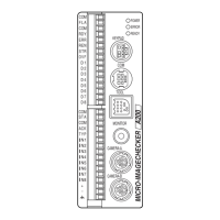
Cross
Specify the X and Y coordinates of the intersection point of a cross to display a cross. The intersection
point can be specified with the cursor, values and the coordinates detected by each checker. For details of
selectable items, see page 266.
Specifying Intersection Point
1.
Select the table to set the intersection point X and Y on the
setting window of Cross, and move the cursor onto "IP X" and
press the ENTER key.
A list of available items is displayed. (The checkers displayed in gray
indicates that they are not unset.)