94
Setting Inspection Conditions
Selecting Display Pattern on Screen Window
Set the display methods of various patterns to be displayed on the screen window in SETUP Menu.
The display methods are selected for the following patterns.
• Arrows indicating the inspection area and scan direction of checkers (including Position Adjustment and
Area Size Adjustment)
• Result of Geometry Calculation
• Figures set in Character/Figure Drawing
• Calibration Scale
• However, in the window to set the above checkers (e.g. when selecting "INSPECTION" > "Geometry
Calculation"), select whether or not to display only the patterns of the specified checker number instead
of selecting "Display/Hide".
1.
Press the F1 key in SETUP Menu.
Image menu is displayed.
2.
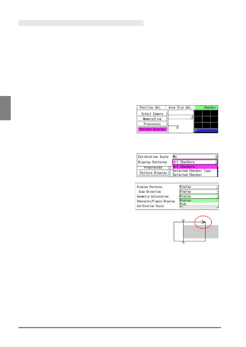
Select "Pattern Display".
3.
Select “Display” or “Hide” for "Pattern Display".
Specify the conditions to display patterns in the checker
setting window ("INSPECTION" > "Checker") and the
checker list window ("INSPECTION" > "Checker List").
All Checkers (Default):
When selecting this, all the set checker patterns are
displayed.
Selected Checker Type:
The checker patterns of the checker type selected in
"Checker Type" are displayed. If Smart Matching
Checker No. 0 is selected, all the checker patterns that
have been set for Smart Matching checker are
displayed.
Selected Checker:
Only the checker pattern for the checker number
currently being selected is displayed.
If Smart Matching Checker No. 0 is selected, only that
checker pattern is displayed.
4.
Select whether to display an arrow to indicate the
scan directions of checkers or not in "Scan
Direction".
Target Checker
Binary Edge / Gray Edge / Connector (Gray Edge) /
Smart Edge (Circle) / Smart Edge (Line)
5.
Select “Display” or “Hide” for "Geometry Calculation" and "Character/Figure Drawing".
In the window after selecting Geometry Calculation or Character/Figure Drawing, select "All Checkers" or
"Selected Checker" for the condition to display patterns.
6.
Select “No” or “Yes” for “Calibration Scale”.
[Yes]: Displays a calibration scale.
[No]: Hides a calibration scale. (Calibration will be executed.)
 Loading...