1. Introduction
Interbus-S
6
1.4 Selectable Data Channels
The length of the process data depends on the Interbus-S software version and the COMPAX Parameter P196 (see also page
81).
The described features are not only valid for the process output data (PAD: data for COMPAX) but also for the process input
data (PED: data from COMPAX
Process output data PAD: Master
⇒
⇒⇒
⇒
COMPAX
Process input data PED: Master
⇐
⇐⇐
⇐
COMPAX
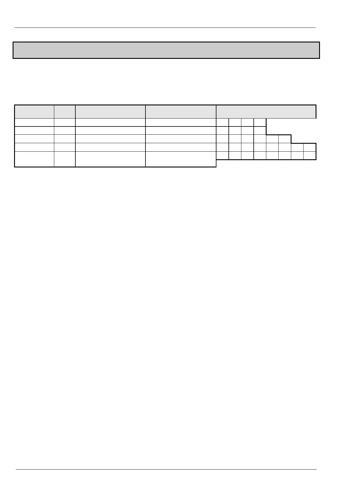
Software-
Version
P196 acyclic data channel Process data length
cyclic data channel
Data channel structure
(split into bytes))
less than 2.00 x 2 Byte PCP communication 2 bytes (1 word)
PCP PCP PD1 PD2
From 2.00 0/1 2 Byte PCP communication 2 bytes (1 word)
PCP PCP PD1 PD2
From 2.00 2 2 Byte PCP communication 4 byte (2 words)
PCP PCP PD1 PD2 PD3 PD4
From 2.00 3 2 Byte PCP communication 6 byte (3 words)
PCP PCP PD1 PD2 PD3 PD4 PD5 PD6
PD1 PD2 PD3 PD4 PD5 PD6 PD7 PD8
From 2.10
Bit 0...2
="1"
no acyclic data channel
(no PCP communication)
8 byte (4 words)
PCP: acyclic data channel:
is used for e.g. configuration.
PD: cyclic process data:
is used e.g. for transferring actual values.
Acyclic data channel (PCP) for parameter data
This data channel will be described via your Interbus-S software. All objects can be transferred through this channel. The
Interbus-S software splits longer objects which are then transferred in several cycles.
Cyclic process data
Only approved objects can be used on the cyclic process data channel. Whether an object has been approved for a PAD or
PED channel is outlined in the respective objective descriptions under the heading PD “depictions” or in the object overview
(page 9 onwards) in the column headed PD.
Assignment of PED and PAD:
There are various ways of loading objects onto the process data channels.
1. Via the COMPAX parameter P135 - P142
These parameters are only accepted by COMPAX after Power off/on.
Setting the process data channels with the COMPAX parameters corresponds to the settings with PED_INI and PAD_INI.
2. Via the objects PE_SELECT and PA_SELECT
These objects allow the PD assignments to be set and/or changed during operation.
Setting: 8 Byte Process data channel (P196 Bit 0...2 ="4")
With P196 Bit 0...2 = "4", the acyclic data channel (PCP) for parameter data is turned off, making a 8 byte-wide process data
channel available.
The process data channel is split into two parts, one of which has two possible assignments, PD1 and PD2, and another part
which can be freely configured for assigning PD3 to PD8.
Assigning PD1 and PD2 with P196 Bit 7
P196 Bit 7="0"
PAD1-2 = STEUERWORT
PED1-2 = STATUSWORT
P196 bit 7 ="1"
PAD1-2 = CPX_STW
PED1-2 = CPX_ZSW
Assigning PD3 to PD8
The assignment is conducted as described above under the heading " Assignment of PED and PAD", but taking into
consideration that the number of bytes to be assigned have all risen by 2.
In addition to this mode of operation (P196 Bit 0...2 ="4"), 2 new objects (for more details see page 64 onwards) are available,
which may be assigned to the process data:
♦
OBJECT_REQ: For PAD for transferral of any object (max. length of data 4 bytes) to COMPAX.
♦
OBJECT_RSP: For PED as an acknowledgement for write access through OBJECT_REQ or as an answer to read access
through OBJECT_REQ.

 Loading...


