Previous Page Table of Contents Section Contents
Back
Index Next Page
LIFEPAK 500 automated external defibrillator Parts Lists and Assembly Diagrams
12-65
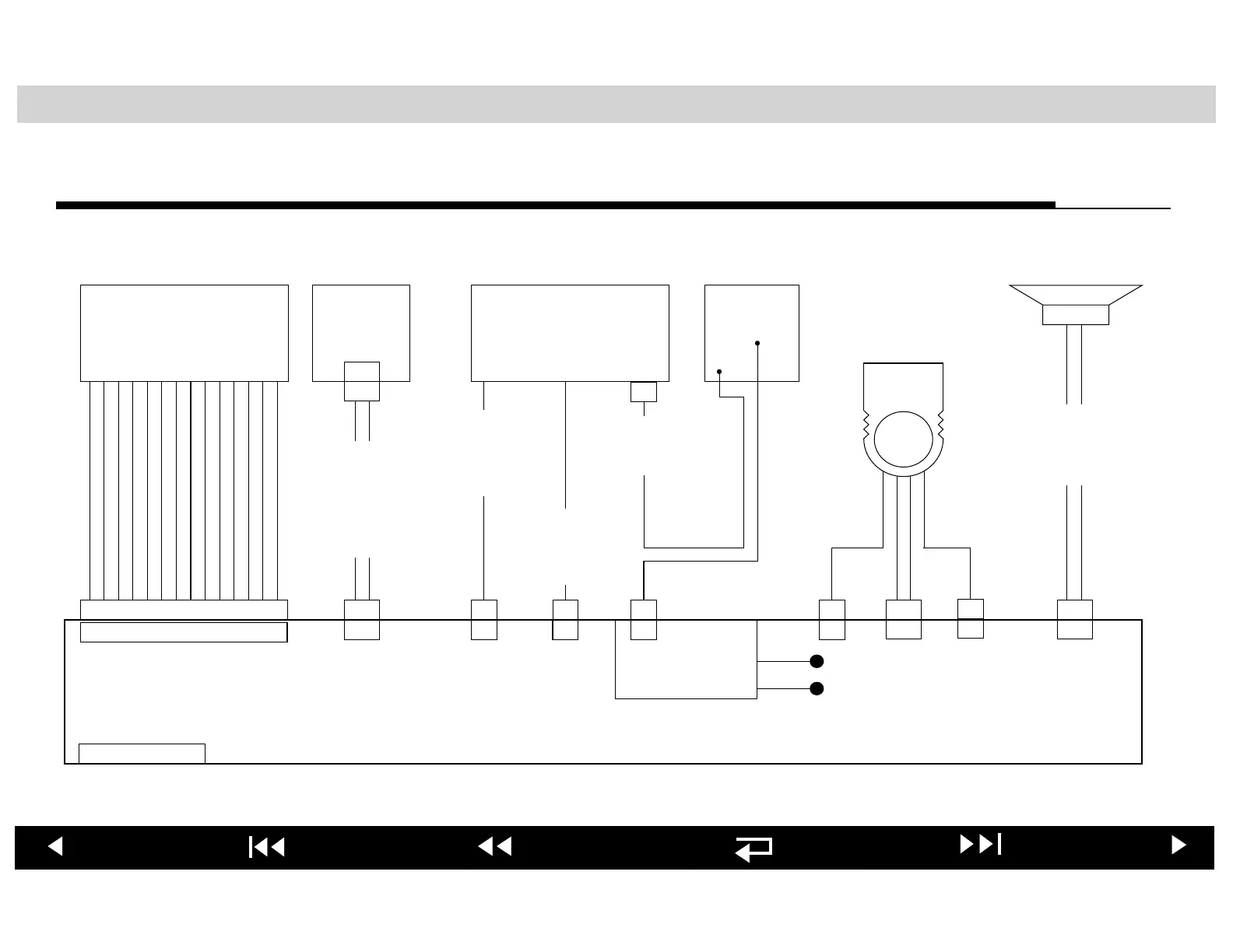
LIFEPAK 500 AED Interconnection Diagram—Monophasic AED
LCD BATTERY CAPACITOR INDUCTOR
PATIENT-CONNECTOR
PAK 804285
A02
W03
QUIK-COMBO
PN 3006144
1 2 3 4 5 6 7 8 9 10 11 12 13 14
1 2 3 4 5 6 7 8 9 10 11 12 13 14
1 2
1 2
P6
J6
P12
J12
P16
J16
P15
J15
1 2
1 2
P9
J9
1 2
1 2
P3
J3
1
1
P1
J1
1
1
P4
J4
1
1
P2
J2
1 2 3 4 5 6 7 8 9 10
J7
MAIN PCB
1
1
P5
J5
1
1
P14
J14
P13
WIRE-HARNESS
INDUCTOR
PN 3005361-005
STERNUM APEXTXDRXD
C1- C1+ C1+ 1 2
1 2 3 4
RELAY
+
-
WP1
WP2
PN 3005535
A01
W04
WIRE-HARNESS
SPEAKER/MAIN-PCB
PN 3005361-001
W01
WIRE
HARNESS
BATTERY
PLATE
PN 3005361-002
W02
W05
WIRE-HARNESS
CAPACITOR #1
PN 3005361-003
WIRE-HARNESS
CAPACITOR #2
PN 3005361-004
W06