Previous Page Table of Contents Section Contents
Back
Index Next Page
LIFEPAK 500 automated external defibrillator Parts Lists and Assembly Diagrams
12-63
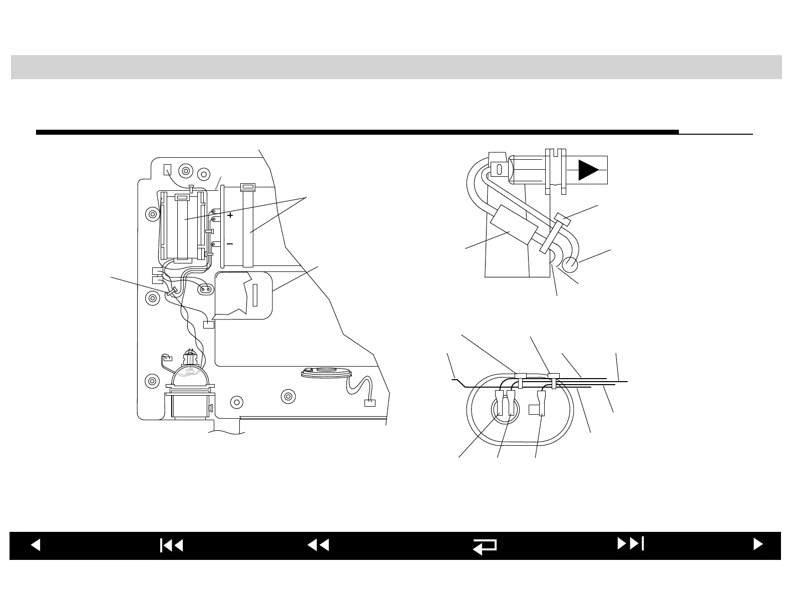
Wire Routing and Tie-Wrap Placement—Monophasic AED
22 (3×)
21 (5×)
23
J4
J1
J5
J3
J2
J9
J12
To J14
Connectors shown in relative position on under-
side of the main PCB, which is not shown.
White
to J3
Red to J2
Red to J4
21 (REF)
Ferrite
Bead
(REF)
To Inductor
To J5
To J1
To J2
To Patient
Connector
Pin 4
Tie-Wrap #2
Tie-Wrap #3
C1+
C1-
P13
Note: It is critical that the wire connected to J5 on the Main PCB is oriented so that it exits the PCB and routes directly down
toward the lower case cavity. It is important that the wire does not loop back onto or near the PCB itself.