User’s Manual of MGSW-24160F
37
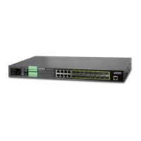
2.2.5 Wiring the Digital Input / Output
The 6-contact terminal block connector on the rear panel of MGSW-24160F is used for Digital Input and Digital Output. Please
follow the steps below to insert wire.
1. MGSW-24160F offers two DI and DO groups. 1 and 2 are DI groups, 3 and 4 are DO groups and 5 is GND (ground).The 6
pin is useless.
Figure 2-11 Wiring the Redundant Power Inputs
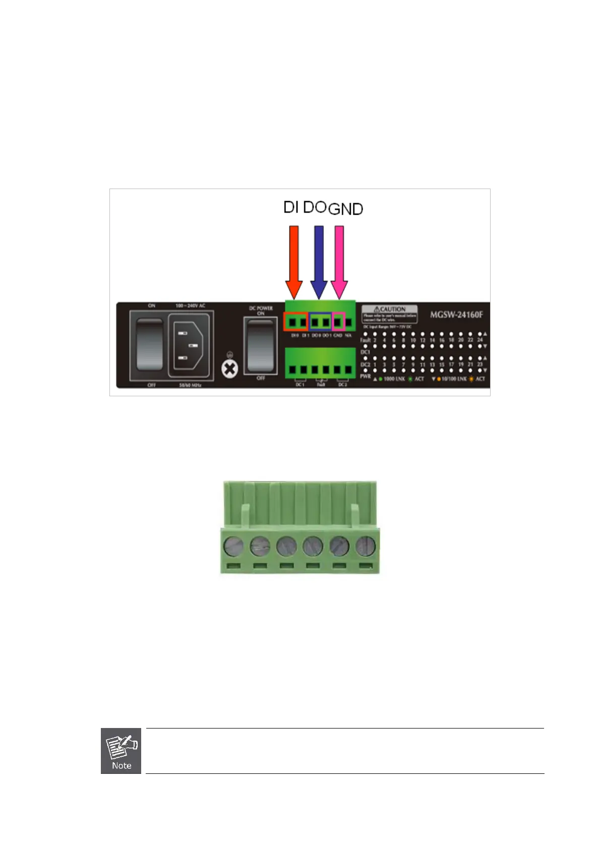
2. Tighten the wire-clamp screws for preventing the wires from loosing.
1 2 3 4 5 6
DI0 DI1 DO0 DO1 GND N/A
Figure 2-12 6-Pin Terminal Block DI / DO Wiring Input
3. There are two Digital Input groups for you to monitor two different devices. As following topology shows how to wire DI0
and DI1. We use MGSW-24160F to be an example for describing DI application.
The accecpting voltage of 2 digital input groups is -30V DC maximum, current is 8mA maximum.
The accepting voltage of 2 digital output groups is -30V DC maximum, current is 200mA maximum.
 Loading...