7
7.71
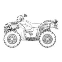
REAR GEARCASE INSTALLATION
1. Place the gearcase in the frame as shown by starting
the lower portion first.
2. Using your hand, press down on the inner PVT cover
and position the gearcase back into the frame while
taking care not to damage the inner PVT cover.
NOTE
Do not use a pry bar to flex the inner PVT cover as
damage to the cover will occur.
3. Continue to position the gearcase back into the
frame until the top portion clears the frame.
4. Position the gearcase in the frame and align the
mounting holes of the gearcase to those in the
frame.
5. Inspect the inner PVT cover for any signs of damage
caused during removal or installation. If any burs are
present, carefully clean them up with a flat hand file.
6. Continue the installation procedure by reversing the
“Gearcase Removal” procedure at the beginning of
this section. Refer to the following installation steps
for torque specifications. Gearcase Removal (XP
Models), page 7.62
7. Install the gearcase through-bolt mounting fasteners
and torque to specification.
NOTE
Use the longer bolts (150 mm) in the top and the
shorter bolts (125 mm) in the bottom.
TORQUE
Gearcase Mounting Fasteners:
40 ft. lbs (54 Nm)
8. Install the right rear drive shaft into the gearcase and
the upper A-arm onto the bearing carrier. Torque the
bearing carrier through-bolt fastener to specification.
TORQUE
Rear Upper A-arm to Bearing Carrier:
37 ft. lbs (50 Nm)
9. Install the left rear drive shaft and suspension
assembly. Torque the upper and lower A-arms to
specification.
TORQUE
Rear Upper & Lower A-arms to Frame:
37 ft. lbs (50 Nm)
FINAL DRIVE

 Loading...