DANGER
WARNING
Information
The Wallbox can be connected in single-phase or
3-phase conguration, see Power Supply > Setting
the mains conguration.
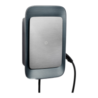
Please refer to the circuit diagram when connecting
the infrastructure cable g(Fig.13) , g(Fig.14).
Connect the infrastructure cable (3-phase)
Fig.13: Connection terminals (3-phase)
1. Remove 0.48 in of the insulation from the cable
wires.
2. Insert wires with the correct colours into the
terminals in the following sequence from le to
right:
1 L1
2 L2
3 L3
4 N (blue)
5 PE (green/yellow)
3. Tighten the screw terminals at the front with a
torque of 2lb- +/-8%.
Connect the infrastructure cable (single-
phase)
Fig.14: Connection terminals (single-phase)
1. Remove 0.48 in of the insulation from the cable
wires.
2. Insert wires into the terminals in the following
sequence from le to right:
TT/TN network:
1 L1
2 N (blue)
3 PE (green/yellow)
IT network:
1 L1 (black) in terminal 3 (brown)
2 N (blue) in terminal 2 (blue)
3 PE (green/yellow) in terminal 1 (green/yellow)
3. Tighten the screw terminals at the front with a
torque of 2lb- +/-8%.
Power supply
Enable/disable earth monitoring
Danger to life due to elec-
tric shock
Using the Wallbox without active earth monitoring
can cause electric shocks, short circuits, res, explo-
sions or burns.
Deactivate earth monitoring in unearthed mains sup-
ply systems only.
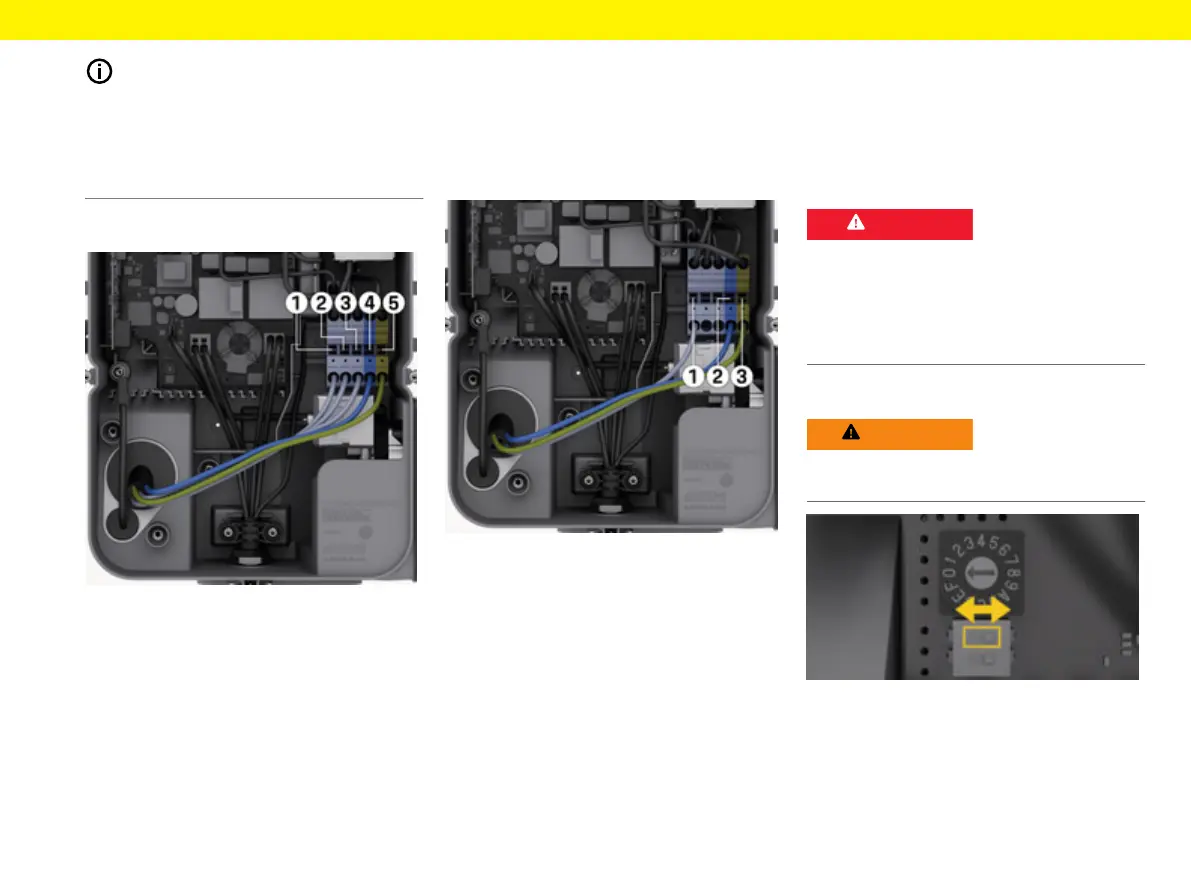
Setting the mains c onguration
Set the mains conguration with the Wallbox in a
voltage-free state only.
Fig.15: DIP switch
Setting the DIP switch
e
Tip DIP switch le or right using tweezers.
 Loading...