1-2 Description – Overview
FlexFit – Linkageless Control – Revision 1.0
PREFERRED
UTILITIES MFG CORPORATION
DD
EE
SS
CC
RR
II
PP
TT
II
OO
NN
Overview
Preferred Instruments' FlexFit 110 is a ame safeguard and linkageless, parallel positioning combustion control system. It is the
next innovative leap to offer the benets of parallel positioning without the high cost or effort of previous parallel positioning upgrades.
Draft control and Oxygen trim options are provided for additional combustion efciency and consistent fuel/air ratios.
The FlexFit replaces existing ame safeguard systems, or it can be used in a new installation. It is designed for any single burner,
one or two fuels, retube or watertube, steam or hot water boiler. It is offered with a complete package of eld devices, or it can be
used with compatible existing equipment. Commissioning is done using the FlexFit's LCD display.
The FlexFit 110 is UL/CSA 60730-1, 2-5 recognized, having both fuel/air ratio control and ame safeguard capabilities. Along with
all other requirements, NFPA 85 compliance is met by having total separation of the fuel/air ratio control and ame safeguard hardware.
The Burner Management System (BMS) (FlexFit-BMS) governs the step-by-step starting sequence for the red equipment.
At the release to modulate state, control is turned over to the combustion control system until the operator elects to shut down the
system, there is no longer a call for heat, or an abnormality results in a BMS-directed shutdown of the equipment. The BMS also
provides ame supervision, system status indication, system and self-diagnostics, and troubleshooting features.
The Combustion Control System (CCS) (FlexFit-CC) is responsible for burner fuel/air ratio control. During the startup and
shutdown sequences, fuel, air, FGR, draft, O
2
trim, or other auxiliary control elements are directed to specic positions by the BMS.
In the modulate state, their positions are governed by the CCS. The FlexFit uses a parallel positioning control system.
The FlexFit-CC provides three analog inputs for various uses (boiler outlet, draft, remote setpoint, 135-ohm ring rate), oxygen
sensor inputs with optional stack temperature, and two analog outputs with paired feedback analog inputs, typically used for VSD
control. Modbus RS485 communication is provided for SCADA, building automation, etc. Additionally, the FlexFit can accommodate
up to seven control servos depending on application requirements. Examples of typical servo applications include the following:
• Fuel 1 servo
• Fuel 2 servo
• Tandem fuel valves (single servo for linked fuel valves)
• Combustion air FD damper servo
• FGR damper servo
• Atomizing steam control servo
• Outlet damper servo for draft control
Typical 4-20 outputs and inputs include the following:
• FD VSD
• FGR VSD
Features
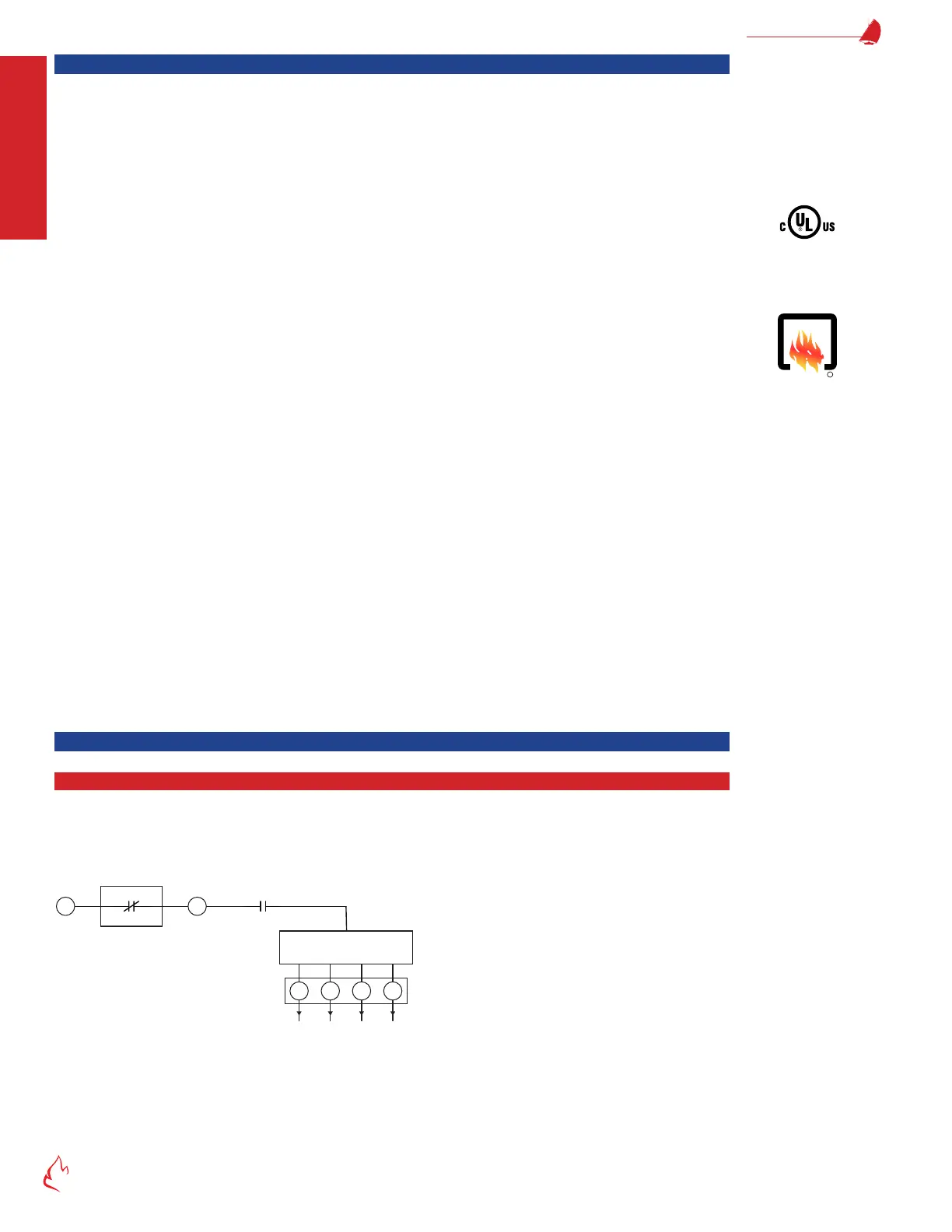
Safety Relay
The safety relay (K1) provides 120 VAC to all ignition source and fuel valve relays. When the safety relay is deenergized, the
120 VAC is removed from the safety power bus. Each safety bus relay output contact is individually monitored, and the safety relay
coil deenergizes if any safety bus relay malfunctions.
Figure 1 – 1 FlexFit 11
3 P
Interlocks
Safety Relay
K1
W 765
Ignition and Fuel Valve
Control Circuit
Ignition Xfmr
Pilot (10 sec TFI)
Pilot (15 sec TFI) (or V2)
Main Fuel Valves (or V1)
0 Safety Relay
XAAF Burner
LISTED
R