2-24 Installation – Servo Installation
FlexFit – Linkageless Control – Revision 1.0
PREFERRED
UTILITIES MFG CORPORATION
II
NN
SS
TT
AA
LL
LL
AA
TT
II
OO
NN
Servo Mechanical Installation
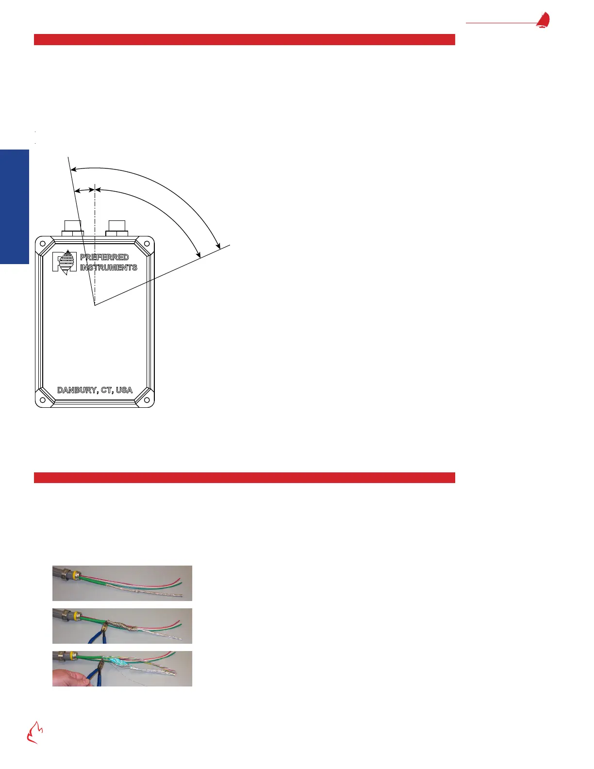
Mechanically connect the servo to the valve or damper such that the shaft will not slip, and the servo does not move under
load. The servo stroke must be between 15 and 180 degrees and cannot stroke inside the forbidden zone. If necessary, rotate the
servo mounting connection 90 or 180 degrees to avoid the forbidden zone. Once the servo installation location and orientation are
nalized, drill and pin the servo shaft coupling to the valve or damper to ensure that alignment does not slip or change. For a list of
common servo couplings and mounting brackets, see the "Parts List" on page A-109.
Figure 2 – 11
Shaft Rotation Forbidden Zone
(Perpendicular to the flat on the shaft)
6
6
°
7
6
°
1
0
°
Servo Forbidden Zone
The servo limit switches and addresses will be congured during the commissioning process. If desired or more convenient,
they may be set at this time. Refer to section "Servo Setup" on page 3-47, if necessary.
Servo Wiring
This section applies to standard servo wiring (P/N: BMU-CABLE-XX). If using the QD1 quick disconnect cables, refer to "QD1
Quick Disconnect Cables" on page 2-26.
Pull one P/N BMU-CABLE-XX and three 16 gage THHN wires through a 1/2" ex conduit with enough slack for servicing. For
daisy chain wiring, use two conduits, with each conduit containing only one P/N BMU-CABLE-XX and three 16 gage THHN wires.
Do not pull two shielded cables through one servo conduit connection.
Before pulling the cables into the servo, prepare the cable ends as follows:
Leaving about 11-12" of cable, remove 8" of green cable insulation.
Push back the braided shield and cut it off. Do not cut off the bare drain wire.
Remove the foil shield. Keep the wire pairs twisted together.