Installation – Flame Scanner/Relay 2-29
FlexFit – Linkageless Control – Revision 1.0
PREFERRED
UTILITIES MFG CORPORATION
II
NN
SS
TT
AA
LL
LL
AA
TT
II
OO
NN
• Choose a sighting location providing an unobstructed view of the ame under all ring conditions. Under no conditions
should the scanner see igniter spark.
• A scanner monitoring a pilot ame should be positioned so that no ame will be detected if the pilot ame is too small to
reliably and safely light the main ame.
• In multiple burner furnaces, choose a sighting angle with the best possible view of the ame of interest and the poorest
possible view of other ames in the furnace.
• The sighting pipe should be inclined slightly downward toward the furnace oor so that unburned particles will not fall into
and moisture will not drain into the scanner cavities.
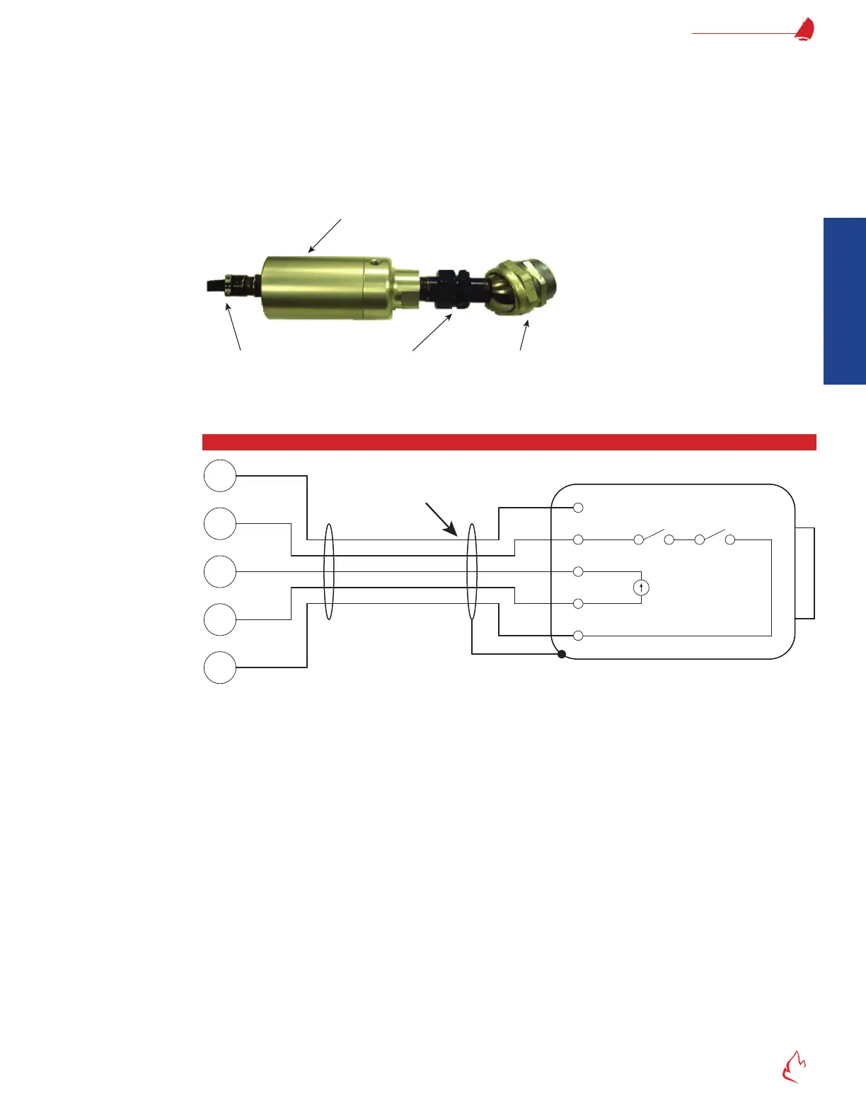
Figure 2 – 17
5000-02
5002-01
5002-73/74
Typical Scanner Mounting
Flame Scanner Wiring
Figure 2 – 18
A
B
C
D
E
Isolated
Loop Powered
4-20mA Output
Neutral
Hot
120V Output
Flame Scanner
OR
YL
RD
BL
BK
Cable
Fl-
Fl+
H
Typical Flame Scanner Wiring
WIRING NOTES:
• The 5002-02/xx scanner cable is available in custom lengths. Replace the last two digits of the model number, xx, with
the desired length in feet.
• All installation, wiring, and service activities must be performed by knowledgeable and qualied technicians.
• All system wiring to and from the FlexFit and scanner should be run in accordance with the National Electrical Code and
all local code requirements.
• Neutral must be grounded.
• Always route sensor signal wiring a sufcient distance away from any type of ignition or other high voltage wiring to avoid
electrical noise interference. Each sensor cable must be run separately from all other wires including other sensors. In
some cases shielded or coaxial cable may be required for long distances or high electrical interference environments.
Each pair of sensor leads should be in their own shielded or coaxial pair.
• Always remove all power to the system before wiring, and never connect or disconnect the scanner when power is present.