vi Specications – FlexFit Specications
FlexFit – Linkageless Control – Revision 1.0
PREFERRED
UTILITIES MFG CORPORATION
Mechanical Specifications
Flame Safeguard Size ...............................................................................................7.2" Length; 5.7" Width"; 3.995" Height
Combustion Control Size ..........................................................................................9.880" Height; 5.054 Width; 1.6" Deep
Panel Cutout .............................................................................................................. 9.375" Height; 4.5" Width; See "Figure 2 – 4
LCD Cutout Dimensions" on page 2-18.
Enclosure Type ..........................................................................................................Flush Panel Mounted
Electrical
Flame Safeguard Terminals ......................................................................................See Table A
Input Power ...............................................................................................................120 VAC (+10%/-15%) 60 Hz
Power Dissipation ......................................................................................................12 W
Maximum Connected Load .......................................................................................2000 VA
Fusing ........................................................................................................................15A Max, Fast Blo
Environmental
Operating Temperature .............................................................................................0 to 140 °F (-18 to 60 °C)
Storage Temperature ................................................................................................-20 to 150 °F (-28 to 65 °C)
Humidity Limits .......................................................................................................... 15 to 95% (non-condensing)
Front Panel ................................................................................................................NEMA 13, IP65
Certification
Testing Authority........................................................................................................UL 60730-1, UL 60730-2-5, CSA E60730-1,
CSA C22.2 No. 60730-2-5: UL le MH45788
Electrical Ratings
• Maximum connected load must not exceed 2000 VA
• Volt-Amp (VA) ratings apply to transformers and similar devices whose inrush current is approximately the same as their
running current.
• VA Pilot Duty ratings apply to relays, solenoid valves, lamps, etc. whose inrush current does not exceed 10 times the
operating current.
• Full Load Amps (FLA) and Locked Rotor Amps (LRA), aka inrush, ratings are intended for motors. VA and VA Pilot Duty
loads may be added provided the total load does not exceed the FLA rating.
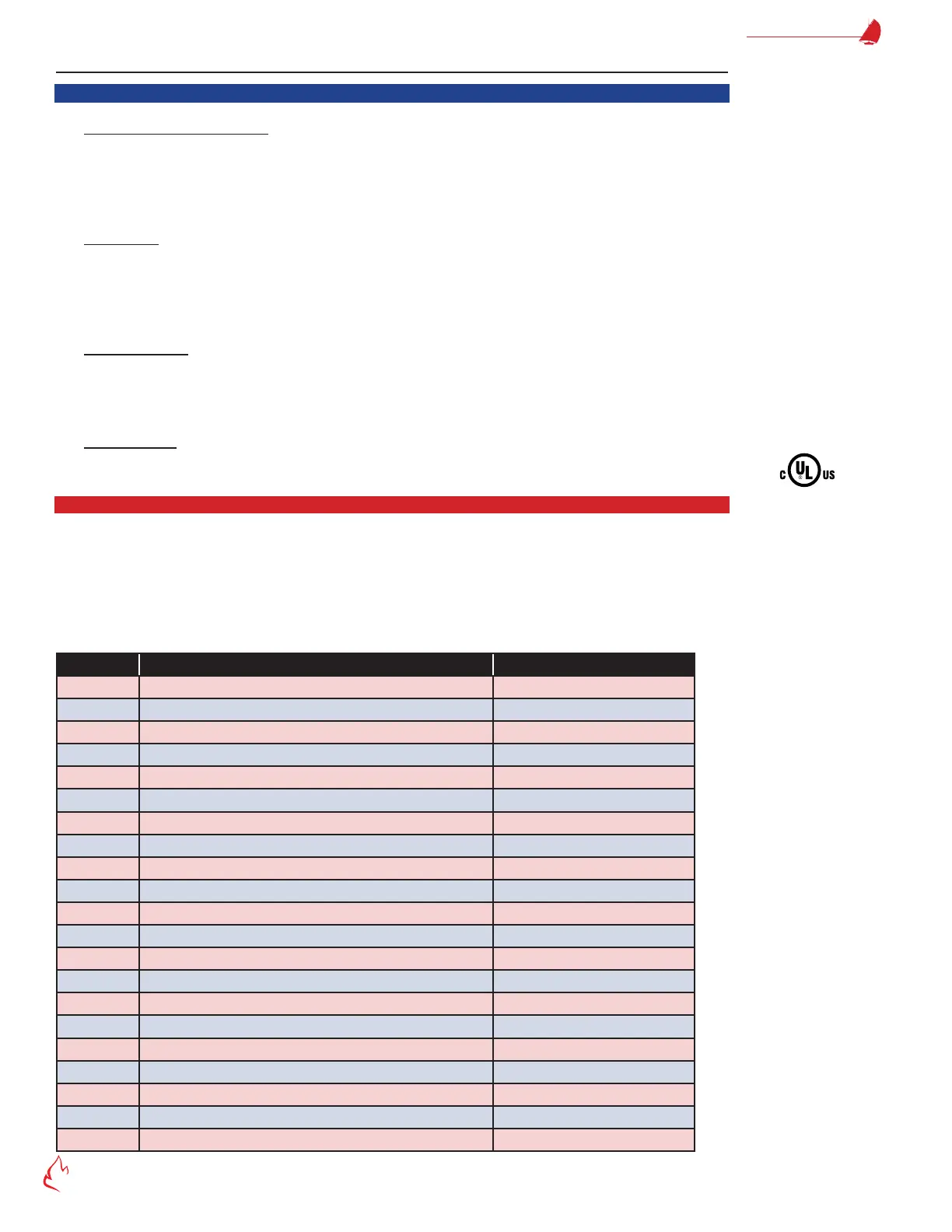
Terminal # Description Rating
G Ground
L2 Line Voltage Common
A Lockout Alarm 120 VAC, 125 VA
L1 Line Voltage Supply 120 VAC, 60 Hz
M Burner Motor (Fan) 120 VAC, 9.8 FLA, 59 LRA (inrush)
13 Burner Controller & Limits Input 120 VAC, 5 mA
P Lockout/Running Interlock Input 120 VAC, 5 mA
5 Pilot Valve/Ignition 120 VAC, See Table
7 Main Fuel Valve 120 VAC, See Table
W Ignition 120 VAC, See Table
X Firing Rate High Fire 120 VAC, 125 VA Pilot Duty
10 Firing Rate Common 120 VAC, 125 VA Pilot Duty
12 Firing Rate Low Fire 120 VAC, 125 VA Pilot Duty
11 Firing Rate Modulate 120 VAC, 125 VA Pilot Duty
16 Valve Proving Pressure Switch Input 120 VAC, 5 mA
17 Call For Heat Input 120 VAC, 5 mA
D Low Fire Switch Input 120 VAC, 5 mA
8 High Fire Switch Input 120 VAC, 5 mA
3 Preignition Interlock Input 120 VAC, 5 mA
6 Pilot Valve/Downstream Fuel Valve 120 VAC, See Table
S1 Unused
XAAF Burner
LISTED