Installation – Flame Scanner/Relay 2-27
FlexFit – Linkageless Control – Revision 1.0
PREFERRED
UTILITIES MFG CORPORATION
II
NN
SS
TT
AA
LL
LL
AA
TT
II
OO
NN
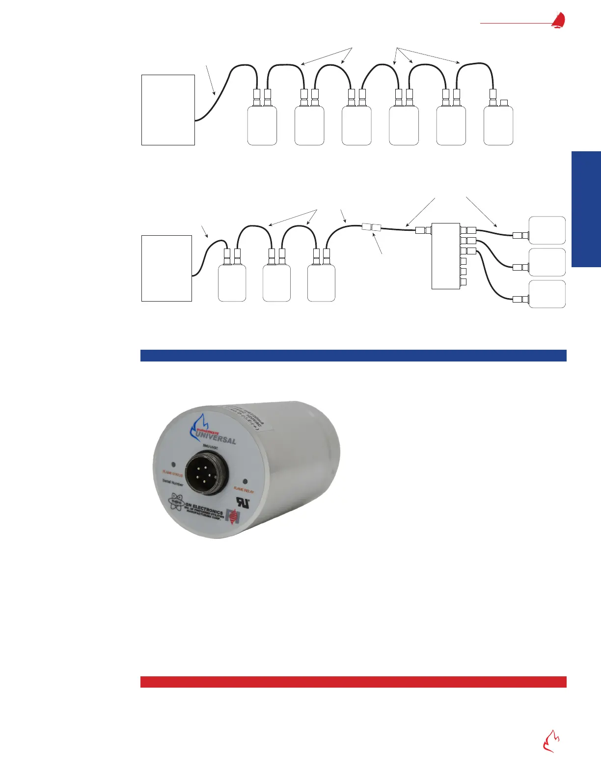
Figure 2 – 14 QD1
QD1-Cable-F-xx
M
F
F
M
Address:
0
M
F
F
M
Address:
1
M
F
F
M
Address:
2
F
F
M
M
F
F
M
M
F
F
M
Address:
5
Address:
4
Address:
3
Burner
Control
Panel
Daisy-chain Connections (Example)
Figure 2 – 15 QD1
QD1-Cable-F-xx
M
F
F
M
Address:
0
M
F
F
M
Address:
1
M
F
F
M
Address:
2
Burner
Control
Panel
F F F F FF
M
IN
A B C D E F
F
M
Address: 5
F
M
Address: 4
F
M
Address: 3
QD1-Cable-MF-xx
BMU-SM-tt-QD1M servos
(BMU-SM-tt-QD1MF servos
can also be used)
Quick Disconnect
Junction Box (QD1-JB)
MMM
F
M
F
QD1-Cable-MF-xx
For long runs, multiple
cables may be
connected together.
Mixed Junction Box & Daisy-chain Connections (Example)
Flame Scanner/Relay
Figure 2 – 16 FlexFit Flame Scanner (Model BMU-UVSC)
The FlexFit can be congured for multiple styles of scanners, including UV, UVSC, and IR. The FlexFit provides a power supply
and the analog inputs for the ame intensity relay display. Preferred Instruments ame scanners are intended for monitoring all gas,
oil, and waste gas red burners. An internal microcomputer controls functions and supervises all essential circuits, verifying they
are always operating correctly. Two LEDs indicate scanner status – ame is proven and ame intensity. The self-checking model
automatically checks the detector and signal processor every 10 seconds.
It has machined alloy housing with seals and a high quality, fused silica quartz lens. There are no scheduled replacement parts
and scanners can be replaced without disturbing wiring.
Flame Status
When a ame is detected, the 4-20mA output will go to a level proportional to ame intensity, and the ame status LED will turn
red. This light will vary in intensity proportional to the level of the ame signal (strength) detected. The ame status LED is a dual color
LED. It will ash green every ten-seconds indicating that the self-check feature is working (the shutter is closing).