2-34 Installation – ZP Oxygen Sensor System Overview
FlexFit – Linkageless Control – Revision 1.0
PREFERRED
UTILITIES MFG CORPORATION
II
NN
SS
TT
AA
LL
LL
AA
TT
II
OO
NN
If the duct is insulated, the nipple and ange are not insulated, and the proper nipple length is used (see chart in Installation
sketch), the detector ange temperature will not exceed 260 °F. If the detector temperature exceeds 260 °F, use one or all the fol-
lowing to lower the temperature:
• Reduce duct radiant heating by insulating exposed ductwork.
• Add another ange gasket.
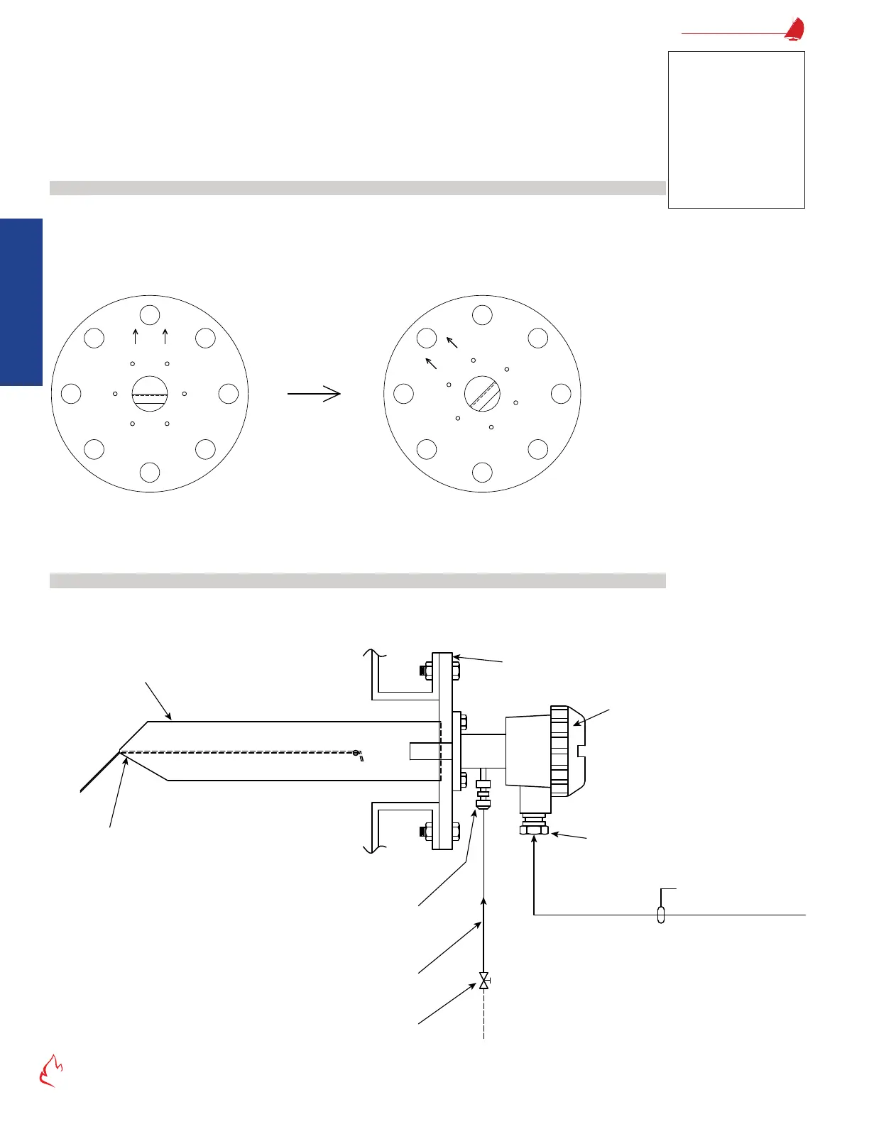
• Rotate the probe one bolt hole to reduce ue gas ow to the detector (see "Figure 2 – 26 Rotating the Oxygen Probe").
Rotating the Probe to Lower Detector Flange Temperature
If the ue gas velocity in the duct is unusually high, the higher ow rate through the probe and past the detector can cause
detector overheating. Rotating the probe ange one bolt hole to purposely misalign the probe tip will reduce the ue gas ow rate
through the probe.
If the probe is horizontal, rotate it counter-clockwise. The detector has an opening for atmospheric air on the lower left side of
the detector housing. Rotating counter-clockwise will keep the inlet pointing downward, minimizing the possibility of water inltration.
Figure 2 – 26
FLOW
FLOW
Normal
High Flow
Rotating the Oxygen Probe
Oxygen Calibration Gas Tubing
When the detector is installed, the detector calibration gas inlet tting and tubing should slope downwards to prevent the entry of
condensed water into the cell. Install copper tubing from the calibration gas port down to an easily accessible location. Terminate the
end with a valve, cap plug, ZP-Cal assembly, or other means to positively prevent ambient air inltration into the calibration gas port.
Figure 2 – 27
Probe
Supplied
Calibration Gas Tube
1/4" O.D. Copper Tube
Connect calibration gas
tube to gas inlet
connection with orifice
installed properly
Cable Gland
Detector
Follow mounting instructions
7-wire Cable
PUMC #190130
Sample Gas
Temperature
1150 °F Max.
Calibration Gas Tubing
Note
The temperature sensitive
label cannot be reused, if
the temperature exceeded
260 °F. After modications
are made, use a new label
or some other means
(thermocouple, surface
thermometer, …) to
measure the temperature.