2-20 Installation – Variable Speed Drive Installation
FlexFit – Linkageless Control – Revision 1.0
PREFERRED
UTILITIES MFG CORPORATION
II
NN
SS
TT
AA
LL
LL
AA
TT
II
OO
NN
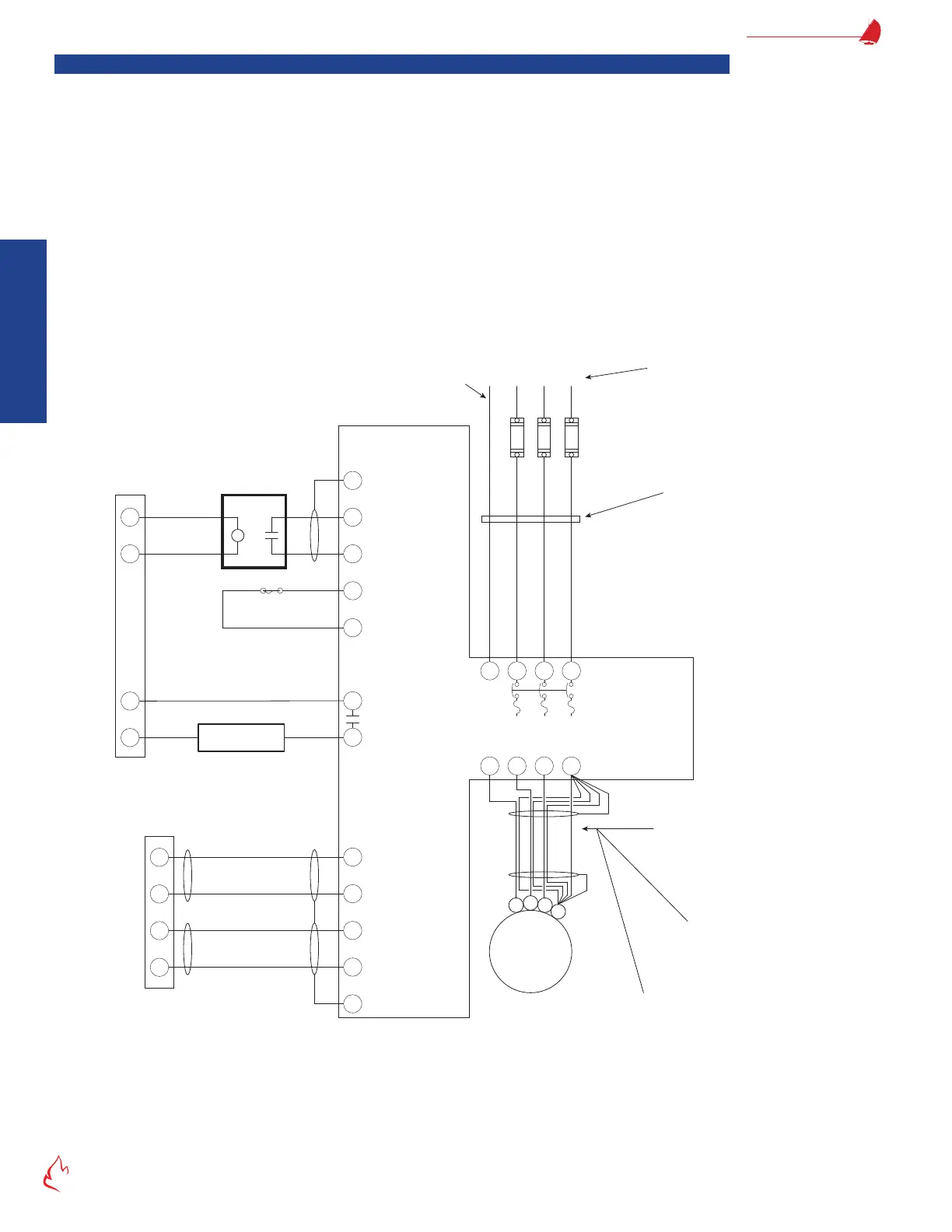
Variable Speed Drive Installation
1. Be sure you have read the notes in section "Electrical Noise Suppression" on page 2-12 and section "Installation Warnings
and Notes" on page 2-13.
2. Connect the blower (fan) output on the FF-BMS (terminal M) to the VSD as shown.
3. For VSDs that have a bypass, the VSD must be congured to output 120 VAC to FSG terminal 26, when it is running in
bypass, and 0 VAC to FSG terminal 26, when it is running in variable speed. This is usually accomplished via a mounted
or user-selectable relay in the VSD controller. See VSD technical documentation for how to accomplish this.
4. On the FlexFit-CC, terminals 132 and 133 are the 4-20 mA output (setpoint) signal to the VSD and terminals 127 and 128
are the 4-20 mA input (feedback) signal from the VSD.
5. If using a second VSD as the Aux 2 device, terminals 134 and 135 are the 4-20 mA output (setpoint) signal to the VSD
and terminals 130 and 131 are the 4-20 mA input (feedback) signal from the VSD.
6. The VSD is a primary source of electrical noise. When running 3-phase cables to the VSD and between the VSD and
motor, all noise suppression notes must be followed.
Figure 2 – 7 FF-11
N
Fan Start
FlexFit-110 Flame
Safeguard
VSD Start
}
FD Fan
Motor
1
2
3
G
M
L2
3
Load Side
Wiring
Line Side
Wiring
The wiring between the VSD and FD Fan
motor must be of a shielded cable
designed specifically for the suppression
of electrical noise associated with a VSD.
e.g. Belden 29520 thru 29532
or AlphaWire V163xx
Do not run load side wiring in conduit with any
other wiring. Use dedicated metal conduit with
Seal-tite connectors. Do not run these wires
through junction boxes that include other wires.
Connect all three bare wire
grounds inside shielded cable
plus shield to both the motor and
VSD ground terminals as shown.
Integral VSD
Disconnect & Fuses
G L2 L3L1
460V–3Φ–60Hz
Earth Ground
Customer supplied circuit protection, input
power, and motor wiring must be selected
in accordance with N.E.C., any applicable
local codes, and the drive current rating.
Do not run in conduit with load side
wiring. Run ground wire directly to
the VFD as shown. Do not run any
low voltage wires in this conduit.
FD Fan Motor Variable Speed Drive
(without Bypass) Wiring (Typical)
}
4-20 mA
Reference Input
+ SP
- SP
- FB
+ FB
FlexFit
Combustion Control
4-20 mA
Output Speed
Indication
}
127
+
-
+
-
128
133
132
FD VSD
4-20 Out
FD VSD
4-20 In
RD
BK
RD
BK
FD Fan VSD
T1 T2
120 Vdc
Coil
G
12
18
+
42
39
53
55
}
P
NOTE: Terminal numbers are
typical of Danfoss FC-Series
VSDs. Applications will vary.
G
Ground
Ground
Burner
Door Switch
Other Running
(Lockout) Interlocks
04
05
VSD Running +
No Alarm +
Start Command
Relay
27
13
+24 VDC
DC Brake Inverse
GT3
0 VSD Wiring (Typical)