Installation – Combustion Control Installation 2-19
FlexFit – Linkageless Control – Revision 1.0
PREFERRED
UTILITIES MFG CORPORATION
II
NN
SS
TT
AA
LL
LL
AA
TT
II
OO
NN
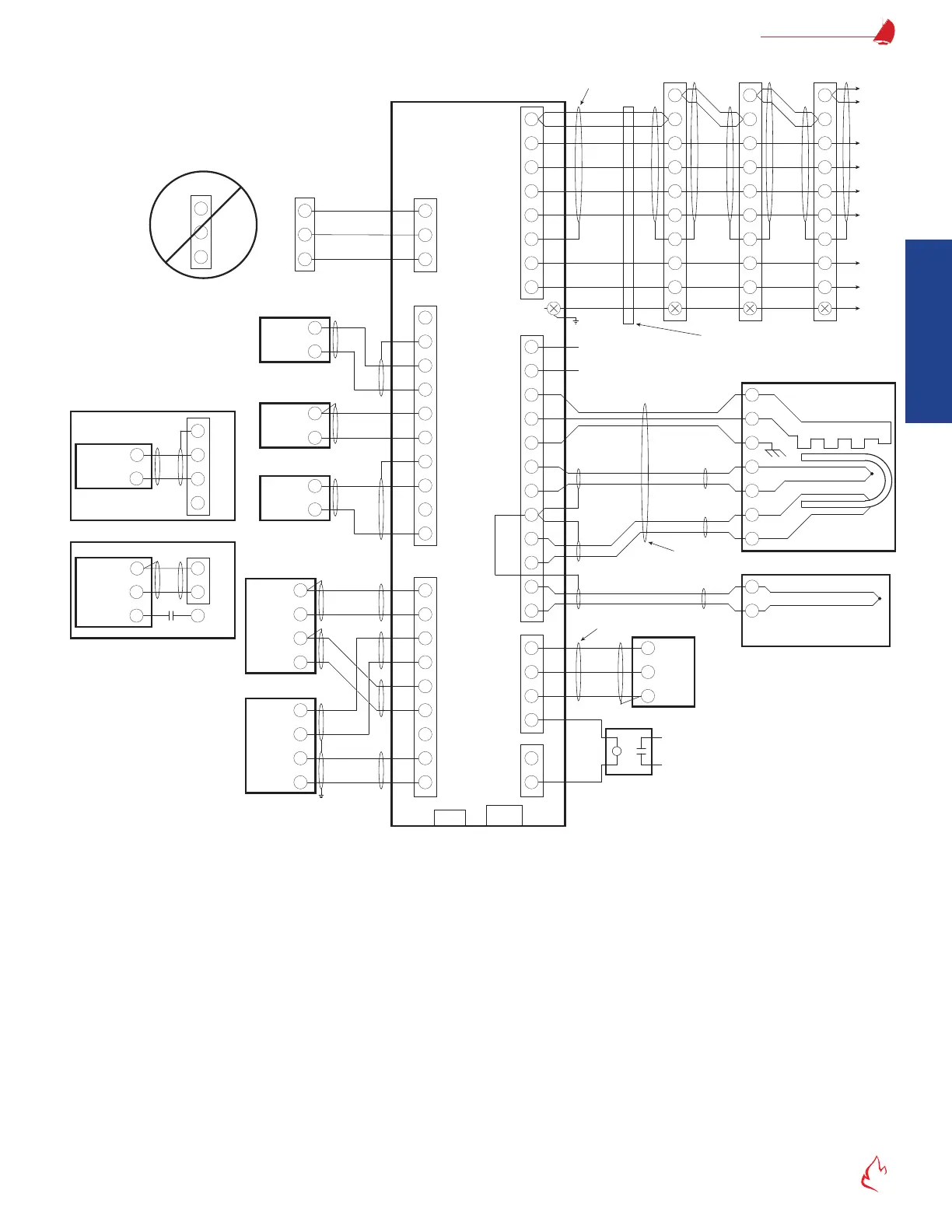
Figure 2 – 6 FF-C
High Fire
Common
Low Fire
B
R
W
Firing Rate
Motor
135-ohm Firing Rate
Controller
Firing Rate Motor is
not wired to FlexFit
Combustion Controller
OUT
24V+
24V-
Comm+
Comm-
Shield
Servo N
Servo H
RS485+
RS485-
Common
FF-CC
N/A
+
-
-
+
ZrO
2
Cell
Type R T/C
Type J T/C
Optional Flue
Gas Temperature
Sensor (PUMC # 104087)
Type J T/C Wire
Type R T/C Wire Green Cable
Gray Cable
7-wire Cable
PUMC # 190130
ZP Oxygen Probe
Heater
WH
RD
RD
WH
GN
BK
RD
BK
RD
120 Vac
220 VA
60 Hz
H
N
4-20mA
2-wire
Xmtr
Shield
+
24V
+
-
Shield
+
5V
24V
135 ohm
Firing Rate
Boiler Steam Pressure
Shield
+
5V
24V
Thermistor
<280°F
Boiler Outlet Water
For Hot Water Boilers
-
+
111
110
109
108
4-20mA
Output
Remote Setpoint
or Firing Rate
4-20mA
2-wire
Xmtr
Draft Pressure
-
+
-
+
- SP
+ SP
- FB
+ FB
24V
24V+
24V-
T/C red -
T/C wht +
Cell +
Cell -
T/C red -
T/C blk +
Htr H
Htr N
120V H
120V N
4-20mA
Feedback
Output
4-20mA
Input
FD VSD
4-20mA
Feedback
Output
4-20mA
Input
Aux 2
BK
RD
BK
RD
WH
OR
BL
Belden #3106A
RS-485
Master
GY
PK
BN
WH
YL
GN
6-wire Cable
PUMC # BMU-CABLE
GROUND
Address 0
All servo wires may be run in the same conduit. No other
AC or DC wires should be combined in the same conduit.
Address 1
Address 2
To Other
Servos
FlexFit Combustion Controller
Wiring (Typical)
Input
Aux 2
4-20 Out
Aux 2
4-20 In
Alarm
24Vdc
Coil
Alarm Relay
Silenced from Keypad
USB
BMS/CC
Link
If a 135-ohm controller is used, no connections to
terminals 108-111 are allowed; if 4-20 mA input or
Thermistor are wired to terminals 108-111, no
connections to terminals B/R/W are allowed.
BAS, SCADA, or
Touchscreen
Shield
+
4-20 mA
Output
P7810 Controller
Other Start
Limits
On BMS
111
110
-
+
OUT
13
-
+
+
-
-
+
+
-
-
+
-
+
-
+
B
R
W
B
R
W
182
181
180
113
112
111
110
109
108
135
134
133
132
131
130
129
128
127
106
107
63
S/G
145
146
147
148
81
82
S/G
143
144
79
80
IN
V+
V-
C+
C-
N
H
OUT
S
IN
V+
V-
C+
C-
N
H
OUT
IN
V+
V-
C+
C-
N
H
OUT
S S
1
2
G
3
4
5
6
-
+
+
-
SH
FD VSD
4-20 Out
FD VSD
4-20 In
Load includes
O
2
Sensor,
up to 7 servos
C Wiring Diagram (Typical)