Installation – Servo Installation 2-23
FlexFit – Linkageless Control – Revision 1.0
PREFERRED
UTILITIES MFG CORPORATION
II
NN
SS
TT
AA
LL
LL
AA
TT
II
OO
NN
A 7-segment (single character) LED display continuously scrolls a message indicating the servo position (Pxx.x), the servo
function (Sxx), the servo address (Axx), and any error messages for that servo (Ex). Below is the key for interpreting these messages.
• Servo Position
Pxx.x = Position in degrees (tenths of a degree reso-
lution)
= 'uu.u' if 'Unknown' (unit has not been 'zeroed'
yet)
= '-xx.x' if negative (suppresses leading zeros)
• Servo Function
F01 = Fuel 1
F02 = Fuel 2
F03 = F1/F2 Valves
F04 = FD Damper
F05 = Aux 1
F06 = FGR Damper
F07 = Draft
F08 = Aux 2
F09 = Aux 3
• Servo Address
Axx = communications address
= 0 thru 9, determined by location in the wiring
daisy chain
= default address is 9
• Error Message
E0 = No errors
E1 = Pot reference voltage out of range (low or high)
Feedback pot wiring incorrect or shorted
E2 = A/D converter error primary versus backup A/D
disagree
E3 = Pot wiper voltage is too high (i.e., above CW
end of pot), greater than V
max
, pot wiring error, bad pot
(open circuit), pot wiper dirty
E4 = Pot wiper voltage is too low (i.e., below CCW end
of pot), less than V
min
, pot wiring error, bad pot (open
circuit)
E5 = Motor vs. Pot direction error, swap the motor CW
and CCW wires.
E6 = Attempting to move into the feedback pot "CW
Forbidden Zone"
E7 = Attempting to move into the feedback pot "CCW
Forbidden Zone"
E8 = J11 jumper not installed
E9 = Servo not communicating with the FlexFit
E10 = Conguration data bad
E11 = Zero data bad
E12 = Limit switch position
E13 = Deadband data bad
E14 = Zero is near "Open"
E15 = Span is too small
E16 = Span is too large
E17 = Measured speed
Note
Errors are checked in
order from E1 to E17.
If there are multiple
errors, the rst error
detected is displayed.
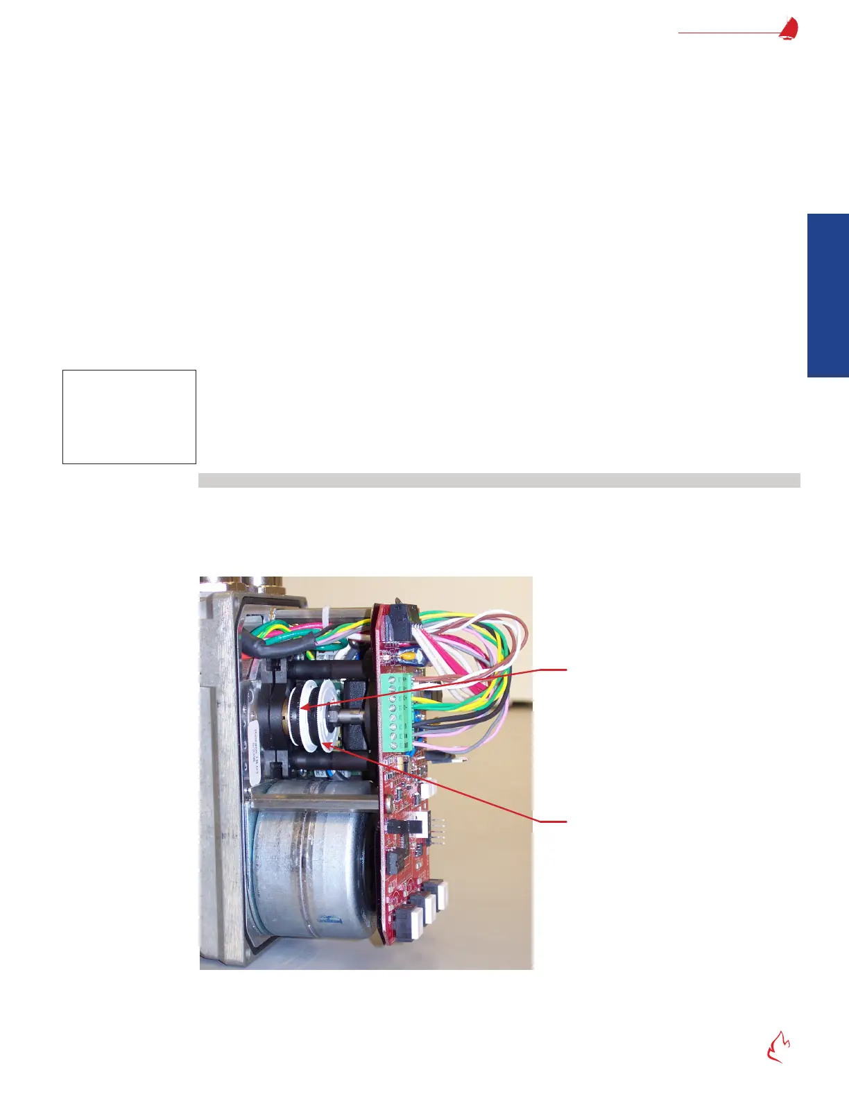
Travel Limit Switches
The FlexFit servos include a clockwise and a counter-clockwise travel limit switch. These switches are factory set for 90° of
servo travel, but the FlexFit will allow the servos to be congured for as little as 15° of travel and as much as 180° for the BMU-SM
servo and a maximum of 90° for the BMU-UM servo by adjusting these travel switches. Always span the servo to take advantage of
the full range of travel of the valve or damper it is driving. If it is determined that the full span of the valve or damper is not required,
then the travel can be limited by how the curve points are entered during commissioning.
Figure 2 – 10
Clockwise (CW)
Travel Limit Switch
(furthest from the circuit board)
Counterclockwise (CCW)
Travel Limit Switch
(closest to the circuit board)
Servo Travel Limit Switches