2-16 Installation – Burner Management System (Flame Safeguard) Installation
FlexFit – Linkageless Control – Revision 1.0
PREFERRED
UTILITIES MFG CORPORATION
II
NN
SS
TT
AA
LL
LL
AA
TT
II
OO
NN
Figure 2 – 2 FF-11
X
Existing
Wiring Base
Low Fire Switch
High Fire Switch
120V Alarm
Start (Recycling) Limits
Running (Lockout)
Interlocks
15 Second Pilot Valve
Burner Motor (Fan)
10 Second Pilot Valve
Master
Switch
L1 (Hot)
L2 (N)
Fuel 1 POCS
Fuel 2 POCS
Fuel Select - 2
Fuel 1 Interlocks
Fuel 2 Interlocks
Pre-ignition Interlock
MV1/MV2 (Main) Fuel Valves
120V, 60 Hz Power Supply
Provide disconnect means and
overload protection as required.
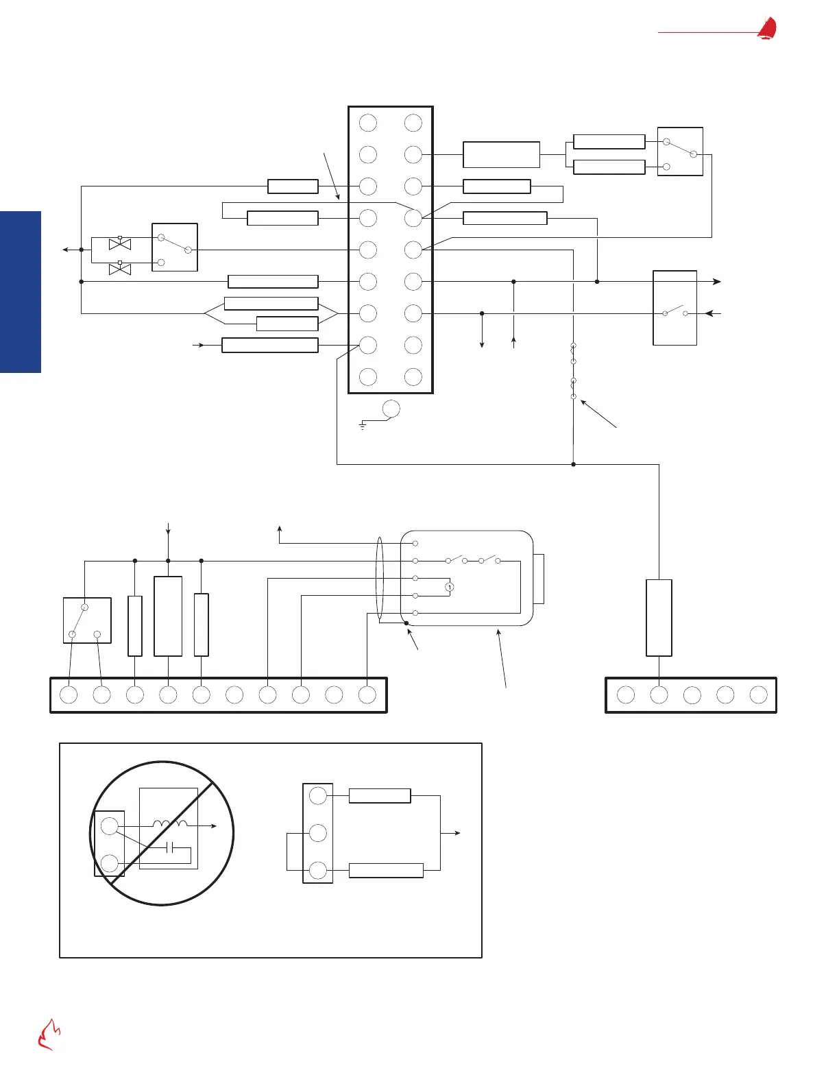
FF-110 Flame Safeguard (BMS)
Standard/Default Wiring (Typical)
*
*
†
Terminals 10, 11, 12, and X are
typically not used with the
FlexFit, but they perform the
same function as an E110.
S2
S1
12
G
10
11
**
If no main fuel valve SSOV has proof
of closure, then jumper terminal 13 to 3.
Ignition Xfmr
6
5
P
D
A
8
Fuel 1 Valve(s)
Fuel 2 Valve(s)
Fuel Select - 3
13
L2
3
M
Optional External
Call for Heat
N/A
N/A
16 17
W
Upper Connector on BMS
†
†
†
†
7
For E110 retrofits, move
this wire from D to M.
L1
L1
L1
L2
**
*Note: Disconnect any existing wires from
terminals S1 and S2; they are not used.
For Direct Spark Ignition
Ignition Xfmr
Main Fuel Valve(s)
5
6
7
L2
If a time delay relay is installed
between terminals 6 and 7, remove
it and wire as shown to the right.
7
6
Time Delay
Relay
L2
**Note: Remove the mod motor. If low fire
proving interlocks are used, then wire them
from M to D. If low fire proving is only by
servo, then jumper M to D. If high fire proving
interlocks (including purge air flow) are used,
then wire them from M to 8. If high fire
proving is only by servo, then jumper M to 8.
Remote Reset
LFH, DHW CFH,
or Warm Standby
FD Fan Mode
F
uel
1
F
ue
l
2
120V = Fixed Speed
0V = VSD
+24V Out
4-20mA In
Upper Connector on BMS
Fuel Select - 1
Flame On
Flame Intensity
A
B
C
D
E
Isolated
Loop Powered
4-20mA Output
Neutral
Hot
120V Output
Flame Scanner
OR
YL
RD
BL
BK
N/A N/A
BMU-UVSC, BMU-UV,
or BMU-IR
Ground to Scanner
Metal Body
FRFl-Fl+
2827262524
L1 L2
Do not wire to any unused terminals
unless noted otherwise.
0 BMS Standard Wiring Diagram (Typical) (Default)