4-64 Parameters
FlexFit – Linkageless Control – Revision 1.0
PREFERRED
UTILITIES MFG CORPORATION
PP
AA
RR
AA
MM
EE
TT
EE
RR
SS
Gas Valve Leak Test Option
The gas valve Proof of Closure Switches (POCS) prove the valves are in their closed positions. However, a valve's POCS do
not prove that the valve seats are not leaking. The FlexFit provides a eld selectable automatic gas valve leak test. Some gas trains
incorporate two Safety Shut Off Valves (SSOVs) with a normally open vent valve arranged so that the area between the two SSOVs
is vented to atmosphere when the burner is off. However, many newer gas trains no longer use a vent valve and depend entirely on
the gas leak test procedure to prove the integrity of the SSOV seats.
If the FlexFit's SSOV leak test is enabled, the leak test is performed after the completion of post purge. If a limit opens during
the leak test, it is postponed until the next pre-purge. Optionally, the leak test can be performed both after post purge and before
pre-purge. The gas leak test for fuel 1 and fuel 2 is enabled or disabled separately with independent test durations.
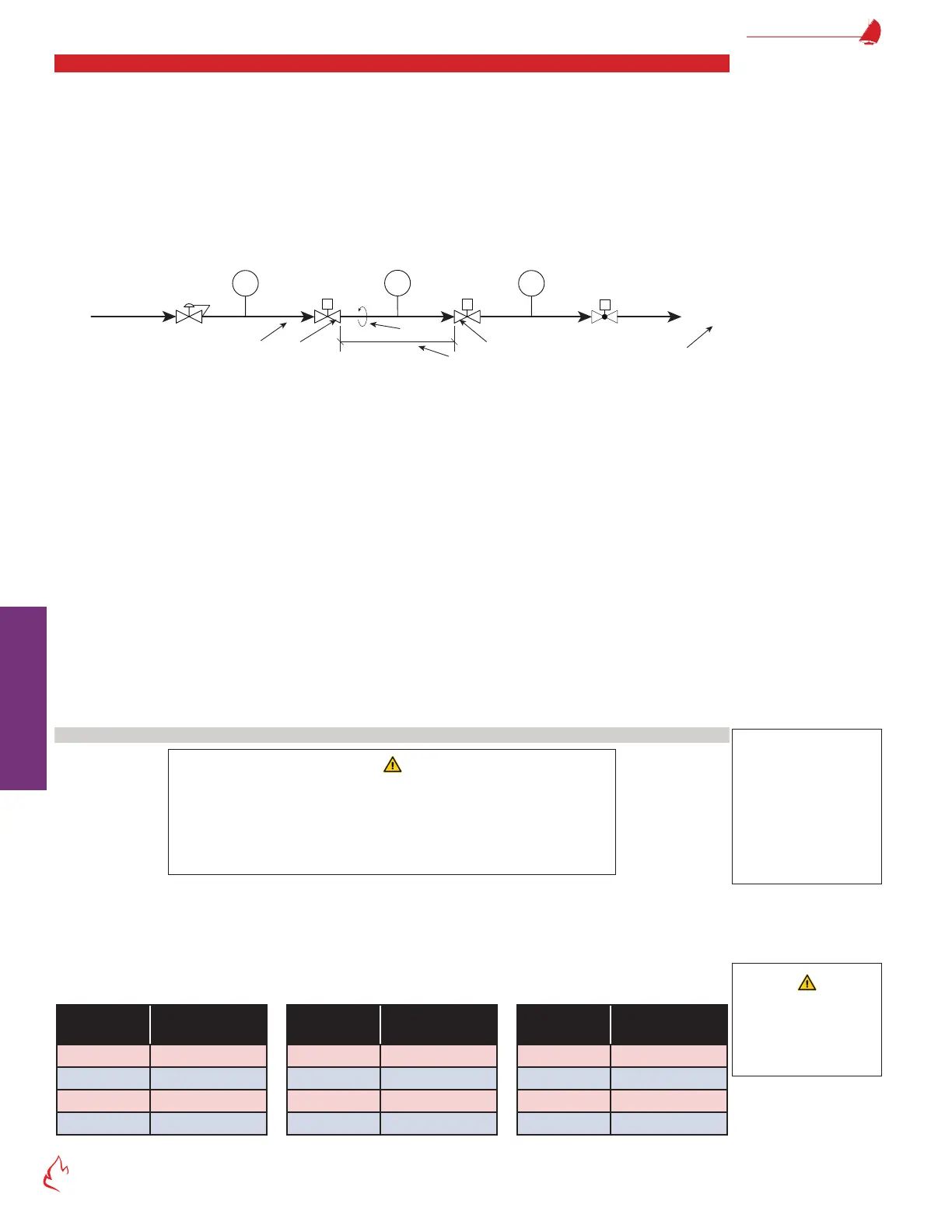
Figure 4 – 1
Gas
Set VPPS to
make at ½ of P
LGP = Low Gas Pressure
HGP = High Gas Pressure
VPPS = Valve Proving Pressure Switch
C
MV1
Upstream
SSOV
MV2
Downstream
SSOV
LGP VPPS
HGP
L
V
UP
V
DOWN
Pressure
Regulator
Gas Flow
Servo
S
P
D
P = Supply pressure to upstream valve (psi)
(divide "WC by 27.7 to get psi)
L = Pipe length between valves (in)
D = Pipe size (diameter in NPT inches)
V
UP
= Volume of upstream valve outlet cavity (ft
3
)
V
DOWN
= Volume of downstream valve inlet cavity (ft
3
)
C = Burner Capacity (ft
3
/hr)
(for natural gas, divide BTUh by 1000 to get ft
3
/hr)
(for LP gas, divide BTUh by 2550 to get ft
3
Typical Gas Train with No Vent Valve
The leak test involves starting the FD fan, which will remain running throughout the test, sending all servos to the low-re
position, and waiting for the non-recycling interlocks to make. The FlexFit will then test the upstream safety shut off valve by opening
and closing the downstream SSOV to vent pressure between the two SSOVs. It will then wait for the leak test duration, verifying
the Valve Proving Pressure Switch (VPPS) is open throughout the test period. Next, the FlexFit will test the downstream SSOV by
opening and closing the upstream SSOV to pressurize between the two SSOVs. It will then wait for the leak test duration, verifying
the VPPS is made throughout the test period. If a leak is detected in either valve, the FlexFit will lockout. Otherwise, upon completion,
the FlexFit will place the burner in the appropriate next state (standby or purge). See "Figure 1 – 4 FlexFit 110 Flex Sequence Timing
Diagram" on page 1-7.
Parameters "P1.3.9 Fuel1 Leak Test Option" and "P1.3.11 Fuel2 Leak Test Option" enable or disable the SSOV leak test and
select if it is performed after post purge or both after post purge and pre-purge. The gas leak test procedure requires both start and
running interlocks to be made throughout the test; therefore, the call for heat option must be used to allow post purge leak testing to
occur (a loss of CFH causes a shutdown but the start interlock is still made). The test duration should be calculated as described below.
Timing Calculations
WARNING
A leaking gas valve can result in an explosion or re. The gas valve leak test is
intended to detect a leak at a rate of 0.1% of high re or more, provided that the
recommended time for the test is programmed into parameters "P1.3.10 Fuel1
Leak Test Sec" and "P1.3.12 Fuel2 Leak Test Sec". If the programmed time is less
than that determined from this calculation, a dangerous leak can go undetected.
The rst step in calculating the valve proving test time is the get the length of the pipe (inches) between the SSOVs, pipe diameter
(NPT inches), supply pressure to the upstream valve (psi) (divide "WC by 27.7 to get psi), and the burner capacity (ft
3
/hr) (divide BTUh
by 1000 to get ft
3
/hr for natural gas or by 2550 to get ft
3
/hr for LP gas). You will need to refer to the SSOV technical documentation
or contact the SSOV manufacturer to determine the SSOV inlet and outlet cavity volumes (ft
3
).
Referencing "Table 4 – 1 Total Pipe Area", determine the pipe internal cross-sectional area (A), and calculate the valve train
volume (V) using the formula in "Figure 4 – 2 Valve Train Volume Calculation".
Table 4 – 1
Pipe Diam.
(Inches)
Area
(Sq. In.)
3/8 0.191
1/2 0.304
3/4 0.533
1 0.864
Pipe Diam.
(Inches)
Area
(Sq. In.)
1.25 1.498
1.5 2.036
2 3.356
2.5 4.788
Pipe Diam.
(Inches)
Area
(Sq. In.)
3 7.393
4 12.73
5 19.63
6 28.28
Total Pipe Area
NOTE
It is best to let the burner
manufacturer determine
the leak test time. If
that is not possible, this
calculation is provided
for the commissioning
technician to make the
timing calculation.
WARNING
Explosion Hazard! A
leak can cause severe
injury, death, and
property damage.