Installation – ZP Oxygen Sensor System Overview 2-35
FlexFit – Linkageless Control – Revision 1.0
PREFERRED
UTILITIES MFG CORPORATION
II
NN
SS
TT
AA
LL
LL
AA
TT
II
OO
NN
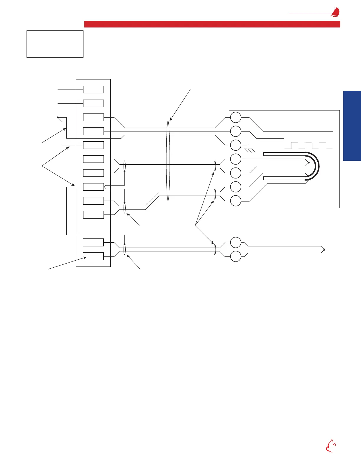
Oxygen Sensor Wiring
The ZP 120 VAC power supply should only be turned off for ZP maintenance or for extended boiler shutdowns. The 120 VAC
power should not be turned off every time the burner is shut down. Excessive power cycling can shorten the life of the ZP detector.
Provide a service loop in the ex conduit at the detector to allow removal/disconnecting the wiring.
Figure 2 – 28
79
148
147
145
S/G
144
143
S/G
82
81
80
146
1
+
-
6
5
4
3
G
2
-
+
ZrO
2
Cell
Type R T/C
Type J T/C
Optional Flue Gas Temperature
Sensor (PUMC # 104087)
Type J T/C Wire
Type R T/C Wire Green Cable
Gray Cable
Internal
3 Amp Fuse
7-wire Cable
PUMC # 190130
note 1
ZP Oxygen Probe
Heater
120 Vac
70W
60 Hz
H
N
G
note 2
note 3
note 4 note 5
W
R
R
W
G
B
R
B
R
+
-
Wiring the ZP Oxygen Sensor to the FlexFit CC
WIRING NOTES:
1. Run all wires in one conduit. 500' maximum wiring length. Avoid splices.
• Use only Preferred Instruments P/N 190130 cable between the ZP and FlexFit. The twisted, shielded cell and T/C
wire with twisted AC wiring prevents electrical noise.
• Multiple ZP cables may be run in one conduit.
• Flue gas temperature wire can be in this conduit if shielded T/C wire is used.
• Do not include any other AC or DC wires in this conduit.
• 1/2" conduit or larger is required for one 190130 cable.
2. Connect the detector ground wire directly to the power supply ground (16 ga. min.)
3. Connect a separate signal-shields ground wire directly to the power supply ground (22 ga. min.). The "S/G" terminals are
connected internally.
4. Connect shields to "S/G". Insulate shields to prevent shorts to the case or other shields.
5. Do not connect shields at the sensor. Insulate shields to prevent shorts to the case or other shields.
6. The ue gas temperature (FGT) sensor is optional. Jumper the FGT input if not used.
7. Shielded cable is not required if run in conduits that do not have: ZP probe wires, AC wires, or noisy DC wiring.
Note
The terminal screws in
the detector head are
M4x0.7 metric screws.