Installation – Servo Installation 2-21
FlexFit – Linkageless Control – Revision 1.0
PREFERRED
UTILITIES MFG CORPORATION
II
NN
SS
TT
AA
LL
LL
AA
TT
II
OO
NN
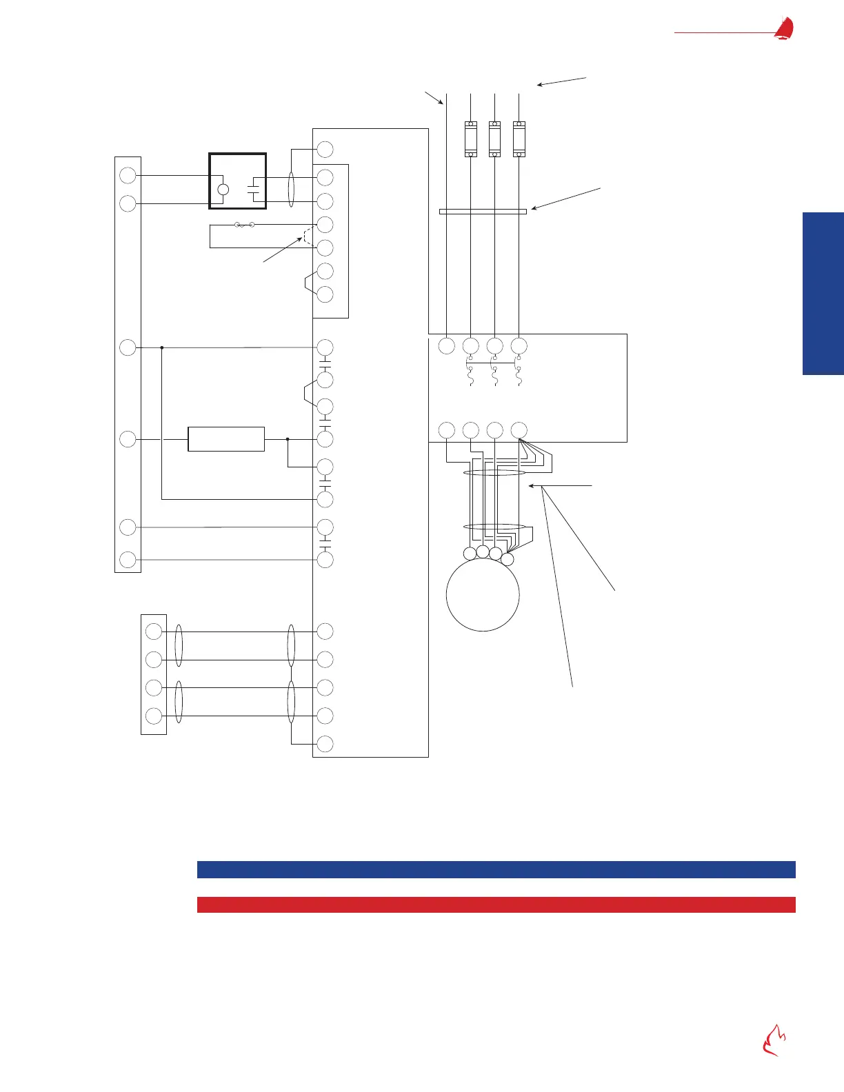
Figure 2 – 8 FF-11
N
Fan Start
FlexFit-110 Flame
Safeguard
VSD Start
in Drive
or Bypass
FD Fan
Motor
1
2
3
G
M
L2
L1
Load Side
Wiring
Line Side
Wiring
The wiring between the VSD and FD Fan
motor must be of a shielded cable
designed specifically for the suppression
of electrical noise associated with a VSD.
e.g. Belden 29520 thru 29532
or AlphaWire V163xx
Do not run load side wiring in conduit with any
other wiring. Use dedicated metal conduit with
Seal-tite connectors. Do not run these wires
through junction boxes that include other wires.
Connect all three bare wire
grounds inside shielded cable
plus shield to both the motor and
VSD ground terminals as shown.
Integral VSD
Disconnect & Fuses
G L2 L3L1
460V–3Φ–60Hz
Earth Ground
Customer supplied circuit protection, input
power, and motor wiring must be selected
in accordance with N.E.C., any applicable
local codes, and the drive current rating.
Do not run in conduit with load side
wiring. Run ground wire directly to
the VFD as shown. Do not run any
low voltage wires in this conduit.
FD Fan Motor Variable Speed Drive
(with Bypass) Wiring (Typical)
}
4-20 mA
Reference Input
+ SP
- SP
- FB
+ FB
FlexFit
Combustion Control
4-20 mA
Output Speed
Indication
+
-
+
-
127
128
133
132
FD VSD
4-20 Out
FD VSD
4-20 In
RD
BK
RD
BK
FD Fan VSD
T1 T2
120 Vdc
Coil
3
4
42
39
53
55
VSD Running +
No Alarm +
Start Command
Relay
NOTE: Terminal numbers are
typical of Danfoss FC-Series
VSDs. Applications will vary.
Ground
Ground
Aux NC Contact
Mounted on
M2 Contactor
(P/N 16874)
26
X55
G
G
}
}
}
}
}
Burner
Door Switch
5
6
Safety
Interlock
Remove Danfoss
factory jumper.
+
-
+
-
Other Running
(Lockout) Interlocks
T3 G
043
(in the Bypass side of the cabinet)
1
2
Aux NO Contact
Mounted on
M2 Contactor
(P/N 16872)
}
Aux NO Contact
Mounted on
M3 Contactor
(P/N 16872)
}
05
0 VSD with Bypass Wiring (Typical)
Servo Installation
Servo Description and Operation
The servos for the FlexFit are unique, with an integrated circuit board that provides controller-to-servo interface and a local
servo control device for the service technician. The servos themselves utilize a proprietary digital communication protocol. The circuit
board receives the FlexFit commands and in turn positions the servo. The servos' sealed potentiometer provides the servo position
feedback signal the system depends upon to assure positioning accuracy and safe operation.