Installation – ZP Oxygen Sensor System Overview 2-33
FlexFit – Linkageless Control – Revision 1.0
PREFERRED
UTILITIES MFG CORPORATION
II
NN
SS
TT
AA
LL
LL
AA
TT
II
OO
NN
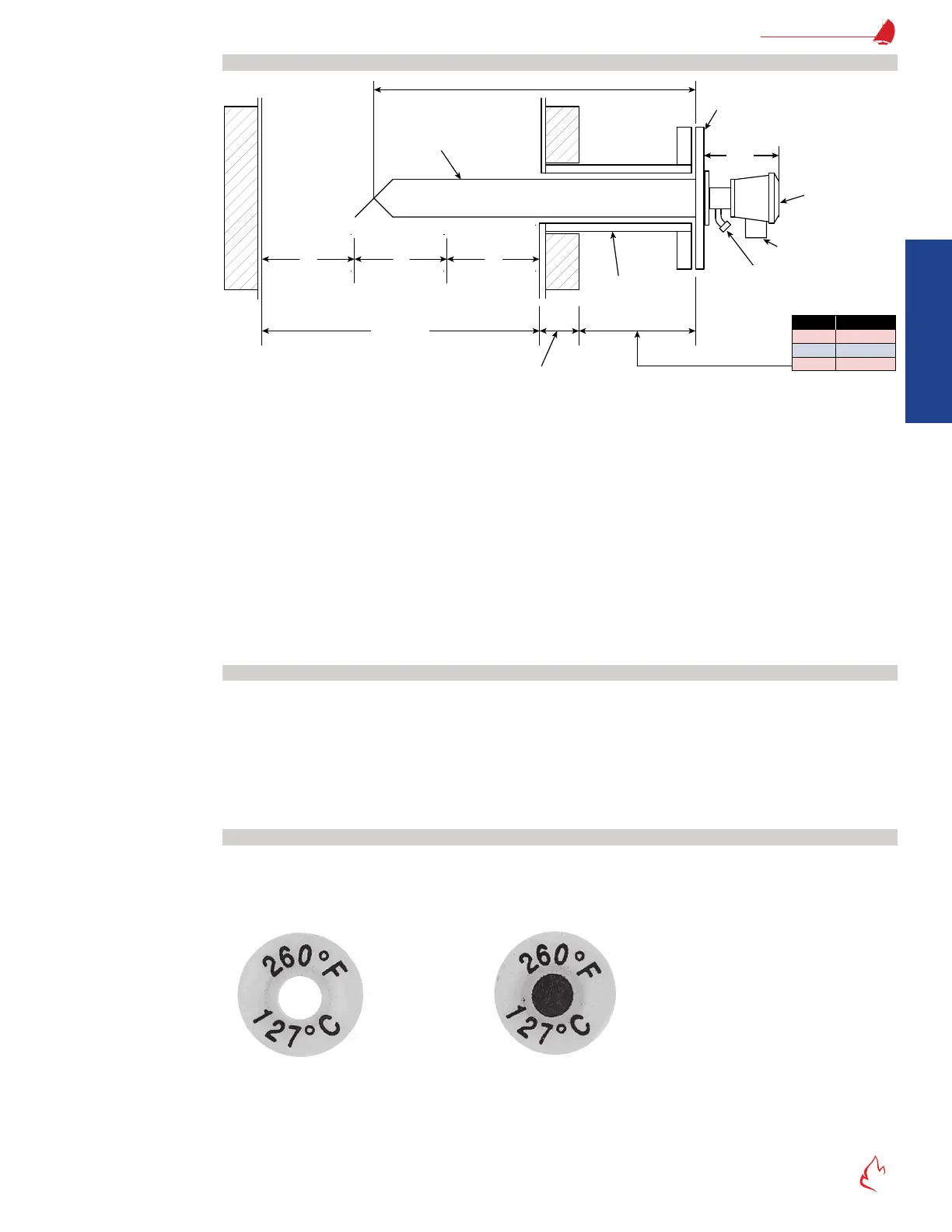
Oxygen Probe Mounting Location
Figure 2 – 24
1/3 1/3 1/3
Stack Width
Insulation
Length
6"
9"
12"
Stack Temp
0-500 °F
500-750 °F
750-1000 °F
Minimum Exposed
Nipple Length
Probe Length
(20, 30, 45, 65, or 90")
2 1/4" dia.
3" – 125# flange
(flat face)
4 3/4"
Terminal Box
1/2" FNPT
Calibration gas
(1/4" Compression)
No Insulation
ZP Oxygen Probe Mounting Location
Locate the end of the probe in the middle one-third of the ue gas stream, as shown in "Figure 2 – 24 ZP Oxygen Probe Mounting
Location" above, and approximately perpendicular to the ue gas ow. The location must be upstream of any ambient air inltration
(and thus oxygen) caused by stack leaks. The probe should be in an area free from any abrupt variations in ue gas pressure or
temperature and ow stagnation pockets. The probe should be mounted in an area of uniform ue gas ow. The probe should not
be subjected to excessive vibration. The standard ZP oxygen sensor is designed for indoor use. If located outdoors, the conduit and
breather port must point down to prevent water inltration.
The detector uses ambient air as a reference, air containing abnormal oxygen levels causes measuring errors. Make sure that
ue gas is not leaking out near the probe.
The ZP probe must always be horizontal or pitched down (away from the detector) to prevent the accumulation of condensed
ue gas water at the detector. Flue gas contains a substantial amount of gaseous water. The ceramic detector cell operates at 800
°C (1472 °F); if liquid water contacts the cell, the ceramic cell will be damaged. The probe should not be vertical, and should not be
pitched down more than 45°, to avoid overheating the mounting ange and internal seals.
Mounting Oxygen Probe Nipple and Flange
The 3" 125# at-faced mounting ange must be mounted on an exposed, non-insulated, nipple of appropriate length, as shown in
"Figure 2 – 24 ZP Oxygen Probe Mounting Location" above. This nipple cools the ue gas to prevent overheating the detector head. The
ZP detector ange must be less than 260 °F to prevent damage to the calibration gas and ambient air seals within the detector head.
The mounting ange bolt holes should be installed so that the ZP ow arrows are aligned with the ue gas ow. This allows
the end of the probe tip to function as a scoop when in the ue gas ow. The tip is designed to direct the ue gas to the detector by
utilizing the dynamic differential pressure produced by the probe tip. The ZP sensor ange has 8 bolt holes but only 4 will be used.
The extra 4 holes allow the user to rotate the probe after installation (see "Figure 2 – 26 Rotating the Oxygen Probe").
Check Oxygen Detector Flange Temperature
The ZP detector ange temperature must be less than 260 °F to prevent long-term damage to the calibration gas and ambient
air elastomer seals within the detector head. After the ZP is bolted to the duct mounting ange, the burner should be operated for
enough time for the ZP detector ange temperature to stabilize (typically 20-40 min.). Observe the temperature sensitive label on
the detector ange (see "Figure 2 – 25 Temperature Sensitive Labels", below).
Figure 2 – 25
Temperature
Temperature
Temperature Sensitive Labels