Description – Burner Management System 1-7
FlexFit – Linkageless Control – Revision 1.0
PREFERRED
UTILITIES MFG CORPORATION
DD
EE
SS
CC
RR
II
PP
TT
II
OO
NN
Figure 1 – 4
Call For Heat
Servo Check
Purge Position
Min.
Max.
High Fire
Low Fire
Purge Hz
Ignition Hz Low Fire Hz
Ignition
10 Sec Pilot
V1 Fuel Valve
(Upstream SSOV)
Running (Lockout)
Interlocks
V2 Fuel Valve
(Downstream SSOV)
FD Fan
Preignition Interlock
(Proof of Closure)
High Fire Switch
Low Fire Switch
Standby
Safe Start
Checks Prestart Purge PTFI MTFI Modulate Post Purge Standby
Flame Signal
Moving
to Purge
Moving to
Ignition
High Fire (Purge)
Low Fire (Ignition)
Modulate
Servos
Start Limits
ALFCO
(Option)
VSD
Note 1
Note 2
Note 4
M
W
5
7
6
P
3
8
D
FR
X
12
11
Out
(with FB)
13
Note 5
Note 3
Note 7
Note 7
Standby Position
Ignition Position
Out
(with FB)
Note 6
Note 8
Post Purge
Leak Test
(Note 9)
PrePurge
Leak Test
(Note 9)
Note 7
Note 10
Note 10
Out
Out
Out
Out
Out
In
In
In
In
In
Out
Out
Out
In
Valve Proving
Pressure Switch
16
In
Note 11
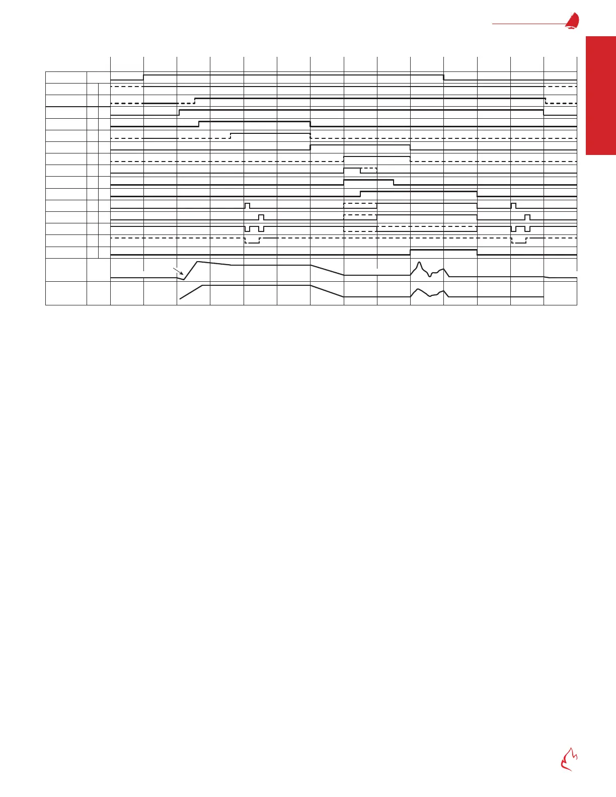
FlexFit 110 Flex Sequence Timing Diagram
FLEX SEQUENCE TIMING DIAGRAM NOTES:
1. If using call for heat, safe start checks will begin once both the start limits (13) input and the call for heat are made.
If not using call for heat, safe start checks will begin once the start limits (13) input is made.
2. Must be low during safe start checks if parameter "P1.1.4 MAF/Run Interlocks Safe Start Test" on page 4-61 is enabled.
3. The FD fan will start after the time delay set by parameter "P1.2.3 FD Fan Start Delay" on page 4-61.
4. Must be low during safe start checks if parameter "P1.1.5 PAF Switch Installed" on page 4-61 is set to Yes.
5. During the purge cycle, the high re switch (purge interlock) can be open for no more than 30 seconds (cumulative). The
purge timer does not run while open.
6. Parameter "P1.3.2 PTFI Ign Xfmr Sec" on page 4-63 sets the PTFI seconds.
7. If direct spark ignition (DSI) is being used, the main fuel valves will open during PTFI and the MTFI state will be skipped.
8. If no main fuel valve(s) (SSOVs) have proof of closure, jumper 120 VAC to (7) and set parameters "P1.2.10 Fuel 1 Proof of
Closure Installed" and "P1.2.11 Fuel 2 Proof of Closure Installed" to No.
9. If leak testing is disabled or not required for the selected fuel, this state is skipped.
The optional gas leak test procedure requires both start and running interlocks to be made; therefore, the call for heat option
must be used to allow post purge leak testing to occur.
For more information on the optional gas leak test and for timing calculations, see section "Gas Valve Leak Test Option" on
page 4-64, and parameters "P1.3.9 Fuel1 Leak Test Option" and "P1.3.11 Fuel2 Leak Test Option".
10. If leak test is disabled, (7) energizes all main fuel SSOVs and (6) remains deenergized (is not used). See section "Burner
Management System (Flame Safeguard) Installation" on page 2-14, for typical wiring diagrams.
11. 120 V (made) = high pressure; 0 V (open) = low pressure.