2-22 Installation – Servo Installation
FlexFit – Linkageless Control – Revision 1.0
PREFERRED
UTILITIES MFG CORPORATION
II
NN
SS
TT
AA
LL
LL
AA
TT
II
OO
NN
The proprietary digital communication protocol allows the servos to be daisy chained to the FlexFit chassis in any order. This
allows the installing contractor to wire the servos in the best way to allow the shortest and cleanest conduit runs. The commissioning
engineer assigns each servo an address and a function during the setup procedure.
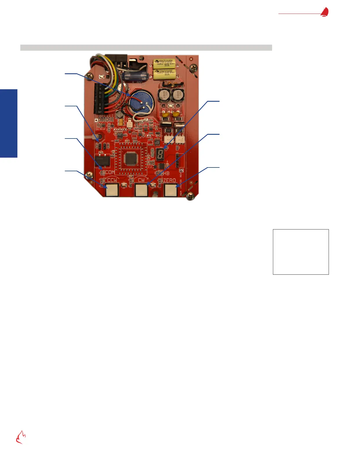
Servo Control Board
Figure 2 – 9
Clockwise “Jog”
Pushbutton
Zero PushbuttonCounterclockwise
“Jog” Pushbutton
Jumper J11
Feedback
Potentiometer
Servo Control Board
The servo board contains three pushbuttons that are used to manually position and zero calibrate the servo.
• CCW – Counter-Clockwise – drives the servo in the CCW direction
• CW – Clockwise – drives the servo in the CW direction
• ZERO – Sets up the servo address and the direction the servo travels to close
Five LED’s provide a continuous status indication of the servo operation.
• CCW LED – ON = Servo motor is being driven counter-clockwise (all modes)
• CW LED – ON = Servo motor is being driven clockwise (all modes)
• ZERO LED – The FlexFit combustion control board has activated the servo zero calibration mode.
Blinking = in zero cal mode, zero position has not been established
ON = in zero cal mode, zero position has been established
• COMM LED – Indicates the status of communication between the servo and the FlexFit
ON = Servo motor is communicating with the FlexFit (all modes)
OFF = The FlexFit has not sent a message to this specic servo for >1 second.
• HB LED – Indicates if the servo is working properly
Blinking 2 times/second = no error
Blinking faster = error
Note
CCW & CW are only active
when the ZERO calibration
mode is active, the servo
is not communicating
with the FlexFit, or the
J11 jumper is removed.