5-86 Troubleshooting – Lockout Data
FlexFit – Linkageless Control – Revision 1.0
PREFERRED
UTILITIES MFG CORPORATION
TT
RR
OO
UU
BB
LL
EE
SS
HH
OO
OO
TT
II
NN
GG
Lockout Data
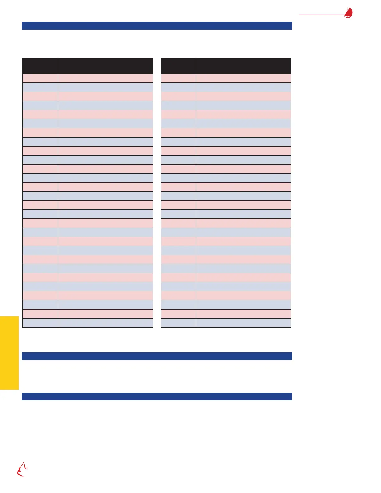
If the condition results in a lockout, a snapshot of the value of virtually every input, output, servo and sensor at the time of the
lockout is stored in the FlexFit memory. Time/date stamped lockout data for each of the last 10 lockouts can be viewed via the LCD
by going to Main Menu > Lockout Data. "Table 5 – 1 Lockout Messages" lists the lockout message data.
Table 5 – 1 Lockout Messages
Message
Number Message Data
0) LOCKOUT
1) BMS State
2) Selected Fuel
3) Scanner 1 %
4) Firing Rate % FB
5) Flue Temp
6) Boiler Outlet Temp/Press
7) O2 Trim PID SP
8) Oxygen
9) O2 Analyzer Normal
10) O2 Trim
11) Scaled O2 Trim
12) Draft
13) Pilot Test Hold
14) Commission Mode
15) Password Level
16) Fuel Demand deg
17) Fuel Feedback Position
18) FD Servo SP
19) FD Servo FB
20) FD VSD Hz SP
21) FD VSD Hz FB
22) FGR Servo SP
23) FGR Servo FB
24) Aux 1 Servo SP
25) Aux 1 Servo FB
26) Aux 2 SP
27) Aux 2 FB
Message
Number Message Data
28) Aux 3 SP
29) Aux 3 FB
30) Draft Servo SP
31) Draft Servo FB
32) Boiler Demand % 135 Ohm/4-20 P7810
33) Remote SP, Firing Rate PID
34) Local SP, Firing Rate PID
35) Firing Rate % Command
36) DI Flame Detected Relay
37) DI Running Interlocks
38) DI FD Fan Type
39) DI Start limits
40) DI Leak Test PS
41) DI Low Fire Switch
42) DI Purge Flow / High Fire Switch
43) DI SSOV POC
44) DHW Start
45) Warm Standby LFH
46) FGR LFH Active
47) Light Off LFH Active
48) Cold Start Cycle Active
49) DHW Override Active
50) Modbus Comm Bad
51) RO Ign Xfmr
52) RO 10s Pilot
53) RO MV1 SSOV
54) RO 15s Pilot/MV2
55) RO FD Fan
I/O Data Display
Navigating to Main Menu > Utilities > I/O Data Display provides a means to view the real-time value of every FlexFit eld wiring
120 VAC input, analog input, and relay output. This provides a means to simultaneously test eld device operation, eld wiring, and
control hardware operation.
Electrical Noise
Electrical noise is a common problem with burner circuitry because of the mix of 120 VAC, low voltage DC, variable speed
drive (VSD) fan motors, and 5,000 to 10,000-volt ignition transformer circuits. Sporadic shutdowns, lost or corrupt data, controller
reboots, and "Internal Error" messages can be caused by electrical noise. If you suspect electrical noise problems, inspect the boiler
wiring for the following issues:
• The shields of all 4-20 mA / 0-5 VDC, Thermistor, Thermocouple, Servo and LCD communications, and scanner cables
should be connected at one end only, as shown on the wiring schematics. All shield foils, braids, and shield drain wires
should be insulated (with either tape or heat shrink) to prevent connections to earth or power ground. Shielded cables
that have been pulled through under-sized conduits or ttings with excessive force can have a torn outer casing inside the