2-18 Installation – Combustion Control Installation
FlexFit – Linkageless Control – Revision 1.0
PREFERRED
UTILITIES MFG CORPORATION
II
NN
SS
TT
AA
LL
LL
AA
TT
II
OO
NN
Combustion Control Installation
1. Be sure you have read the notes in section "Electrical Noise Suppression" on page 2-12 and section "Installation Warnings
and Notes" on page 2-13.
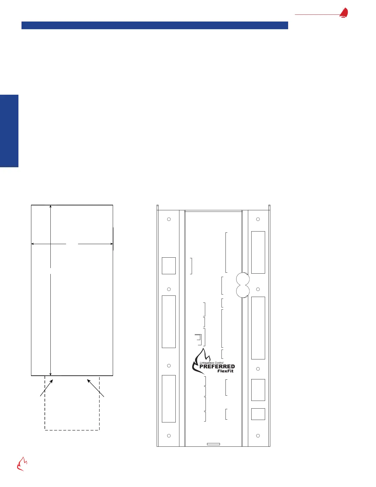
2. Begin by selecting the location for the combustion control keypad/display, and cut a rectangular opening using "Figure
2 – 4 LCD Cutout Dimensions" as a guide.
3. Place the FlexFit-CC into the cutout location and secure it to the door using the provided cinch brackets.
4. During installation, refer to "Figure 2 – 6 FF-CC Wiring Diagram (Typical)" on page 2-19, for a wiring diagram.
5. If a 135-ohm controller is used, wire it to terminals B, R, and W, as shown in the wiring diagram. A ring rate motor is not
needed as the FlexFit will drive the servos as necessary, based on the input.
6. If not using a 135-ohm controller, a boiler outlet sensor may be wired to terminal 108 through 111 as shown in the wiring
diagram. A 135-ohm controller and a boiler outlet sensor may not both be wired to the FlexFit at the same time.
7. See section "Servo Installation" on page 2-21, for servo installation instructions.
8. If using the Preferred Instruments oxygen sensor, see section "ZP Oxygen Sensor Installation" on page 2-32, for ZP
Oxygen Sensor Installation.
9. Continue with the installation of VSDs, RS-485 devices, etc., referencing the FlexFit-CC wiring diagram and any other
included drawings or documentation.
10. Ensure the plug-in terminal blocks are properly inserted before applying power.
11. Connect the 9-pin D-Sub connector between the FlexFit-CC and the FlexFit BMS.
12. The USB port is used for connecting a personal computer, running the FlexFit Edit software, to read or write FlexFit
parameters.
Figure 2 – 4
4 1/2"
9 3/8"
FlexFit-CC
Keypad/Display
Panel Cutout
Enclosure
1.6" deep
behind Panel
"B"
Port
Cable
3" x 3"
Clearance
behind Panel
for Cables
FF-CC Keypad/Display
External Size: 9.9" x 5.1" x 0.38"
LCD Cutout Dimensions
Figure 2 – 5
Oxygen SensorStack
Servos
135 ohm
Firing Rate
Modbus
Aux. Power
Input
3A Slow Blow
Pwr In
FD
VSDAux 2
4-20
In
4-20
Out
Aux 2
FD
VSD
4-20
In
4-20
Out
Draft
4-20
mA
Remote
Demand
4-20
mA
Boiler Outlet
4-20mA
TH
OUT
24V +
24V
‒
Comm +
Comm
‒
Shield
Servo N
Servo H
120V H 79
120V N 80
Htr N 82
S/G
T/C blk + 143
T/C red
‒
144
S/G
Cell
‒
145
Cell + 146
T/C wht + 147
T/C red
‒
148
RS485 +
RS485
‒
Common
24V + 106
24V
‒ 107
Servos
Oxygen
Sensor
GROUND
Htr H 81
R
182 Shield
181 +
180 24V
113
‒
112 +
111 Shield
110 +
109 5V
108 24V
135
‒
134 +
133
‒ SP
132 + SP
131
‒
130 +
129 24V
128
‒
FB
127 + FB
USB
Do Not Use
Alarm 63
W
B
BMS/CC Link
FlexFit-CC Rear View