Installation – Burner Management System (Flame Safeguard) Installation 2-17
FlexFit – Linkageless Control – Revision 1.0
PREFERRED
UTILITIES MFG CORPORATION
II
NN
SS
TT
AA
LL
LL
AA
TT
II
OO
NN
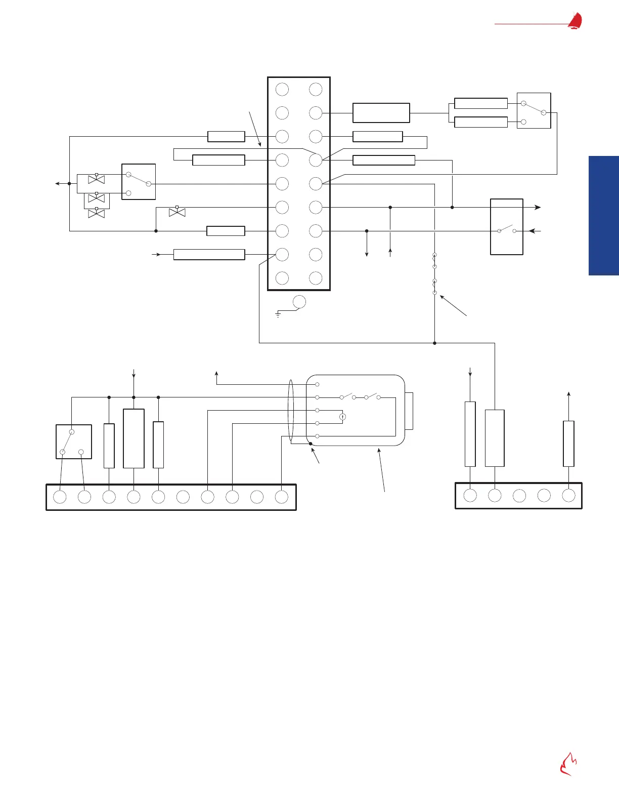
Figure 2 – 3 FF-11
X
Existing
Wiring Base
Low Fire Switch
High Fire Switch
120V Alarm
Start (Recycling) Limits
Running (Lockout)
Interlocks
Pilot Valve
Master
Switch
L1 (Hot)
L2 (N)
Fuel 1 POCS
Fuel 2 POCS
Fuel Select - 2
Fuel 1 Interlocks
Fuel 2 Interlocks
Pre-ignition Interlock
MV1/MV2 Fuel Valves
120V, 60 Hz Power Supply
Provide disconnect means and
overload protection as required.
FF-110 Flame Safeguard (BMS)
Flex Sequence Wiring (Typical)
*
*
†
Terminals 10, 11, 12, and X are
typically not used with the
FlexFit, but they perform the
same function as an E110.
S2
S1
12
G
10
11
***
If no main fuel valve SSOV has proof
of closure, then jumper terminal 13 to 3.
6
5
P
D
A
8
Fuel Select - 3
13
L2
3
M
†
†
†
†
7
For E110 retrofits, move
this wire from D to M.
L1
L1
L1
L2
MV2 Fuel Valve
Gas Valve MV2
(Downstream)
Do not wire to any unused terminals
unless noted otherwise.
**
**
Optional External
Call for Heat
Ignition Xfmr
N/AN/A
16
17
W
Upper Connector on BMS
L2
Leak Pressure Switch
L1
***
Gas Valve MV1
(Upstream)
Oil Valves
*Note: Disconnect any existing wires from
terminals S1 and S2; they are not used.
***Note: If leak test is not being used,
do not wire to terminals 6 and 16.
**Note: Remove the mod motor. If low fire proving
interlocks are used, then wire them from M to D. If
low fire proving is only by servo, then jumper M to
D. If high fire proving interlocks (including purge air
flow) are used, then wire them from M to 8. If high fire
proving is only by servo, then jumper M to 8.
For direct spark ignition, do not jumper
terminals 6 to 7. Wire as shown and use
the flex sequence parameters to control
DSI and timing settings.
Burner Motor (Fan)
Example:
Fuel 1 = Gas
Fuel 2 = Oil
Remote Reset
LFH, DHW CFH,
or Warm Standby
FD Fan Mode
F
uel
1
F
ue
l
2
120V = Fixed Speed
0V = VSD
+24V Out
4-20mA In
Upper Connector on BMS
Fuel Select - 1
Flame On
Flame Intensity
A
B
C
D
E
Isolated
Loop Powered
4-20mA Output
Neutral
Hot
120V Output
Flame Scanner
OR
YL
RD
BL
BK
N/A N/A
BMU-UVSC, BMU-UV,
or BMU-IR
Ground to Scanner
Metal Body
FRFl-Fl+
2827262524
L1
L2
0 BMS Flex Sequence Wiring Diagram (Typical) (Field Selectable)