Parameters 4-77
FlexFit – Linkageless Control – Revision 1.0
PREFERRED
UTILITIES MFG CORPORATION
PP
AA
RR
AA
MM
EE
TT
EE
RR
SS
P3.7.2 hIgh FIre lIMIter, 0-100%
Menu > Advanced Settings > Firing Rate Settings Password Level: Operator Restricted? No
Determines the high re setpoint to which the FlexFit will limit the ring rate.
Options: 30 to 100 [Default 100]
Note "High Fire Limiter, 0-100%" is manually set by the operator.
P3.7.3 +/- aVoId gaP, FIrIng rate
Menu > Advanced Settings > Firing Rate Settings Password Level: Technician Restricted? No
This determines by how much an avoid position is jumped over in the ring rate. Some burner/boiler combinations have an audible
rumble at a specic ring rate due to resonant vibrational energies. If an avoid fuel position was stored in the combustion curve data,
the FlexFit will jump over the avoid ring rate within the range of the "+/- Avoid Gap, Firing Rate".
Options: 0.2 to 5.0 [Default 1.5]
Draft Control
Draft is the term used to describe the movement of gases, usually the products of combustion, through a ue or chimney. The
measurement of draft is expressed in inches water column ("WC) and represents the difference in weight of ue gas and a corre-
sponding column of outside air. The objective of draft control is to maintain a constant furnace or boiler outlet draft pressure (positive
or negative) as the boiler ring rate modulates from low to high re and as outdoor weather conditions change the draft effect.
Typically, the draft pressure is sensed and controlled at either the boiler outlet or in the furnace. A high-quality draft range
transmitter is used to provide a reliable measurement of the draft. Because draft signals are inherently noisy (constantly moving),
it is common to lter the draft signal before it goes to the control block within the controller. However, caution must be used as too
much ltering will result in sluggish control. The draft transmitter should always be located physically higher than the sensing point,
and the sensing lines should be sloped so that condensation in the tubes runs back to the boiler. If the transmitter must be located
below the sensing point, a drip leg, condensation pot, and drain valve should be provided.
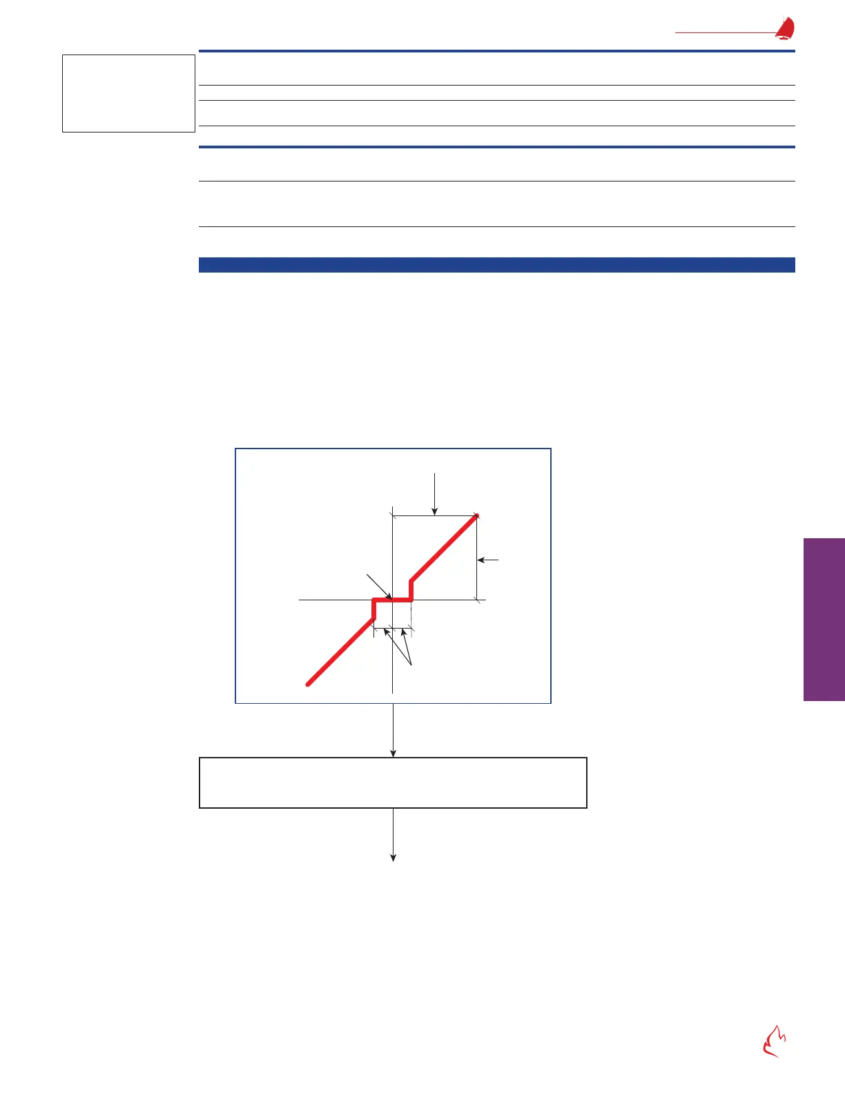
Figure 4 – 6
Error
Measured
Draft
Floating Draft
Set-point
Deadband, Draft (x2)
1/2 Proportional Band, Draft
Max Move per Scan
(based on Sec/90 Deg
Damper Rate Limit, Draft)
+
+
-
-
Once in automatic, the draft damper is positioned to decrease the error
signal (getting it closer to zero) while limiting the maximum servo speed
and not exceeding the minimum and maximum damper positions.
Error
Damper Position
Floating Draft Control
The FlexFit can accomplish draft control by positioning a boiler outlet damper (also called a stack damper) or the damper at either
the inlet or outlet of an Induced Draft (ID) fan. By utilizing oating control, the FlexFit will maintain draft at a setpoint as determined
during boiler commissioning. If the draft error (measured draft minus setpoint) is inside the deadband (see parameter "P4.2.2 Dead-
band, Draft"), the draft damper output doesn't change. If the draft error is outside the deadband, the draft damper position is adjusted
proportionally to the draft error until draft has returned to within the deadband. Additional draft control features include the following:
• Adjustable Purge Positions – Parameter "P4.1.2 Outlet Damper Purge Position" allows the user to set the outlet damper
position for boiler purge.
Note
This does not affect
combustion curves.
It only limits the
maximum ring rate.