Installation – Burner Management System (Flame Safeguard) Installation 2-15
FlexFit – Linkageless Control – Revision 1.0
PREFERRED
UTILITIES MFG CORPORATION
II
NN
SS
TT
AA
LL
LL
AA
TT
II
OO
NN
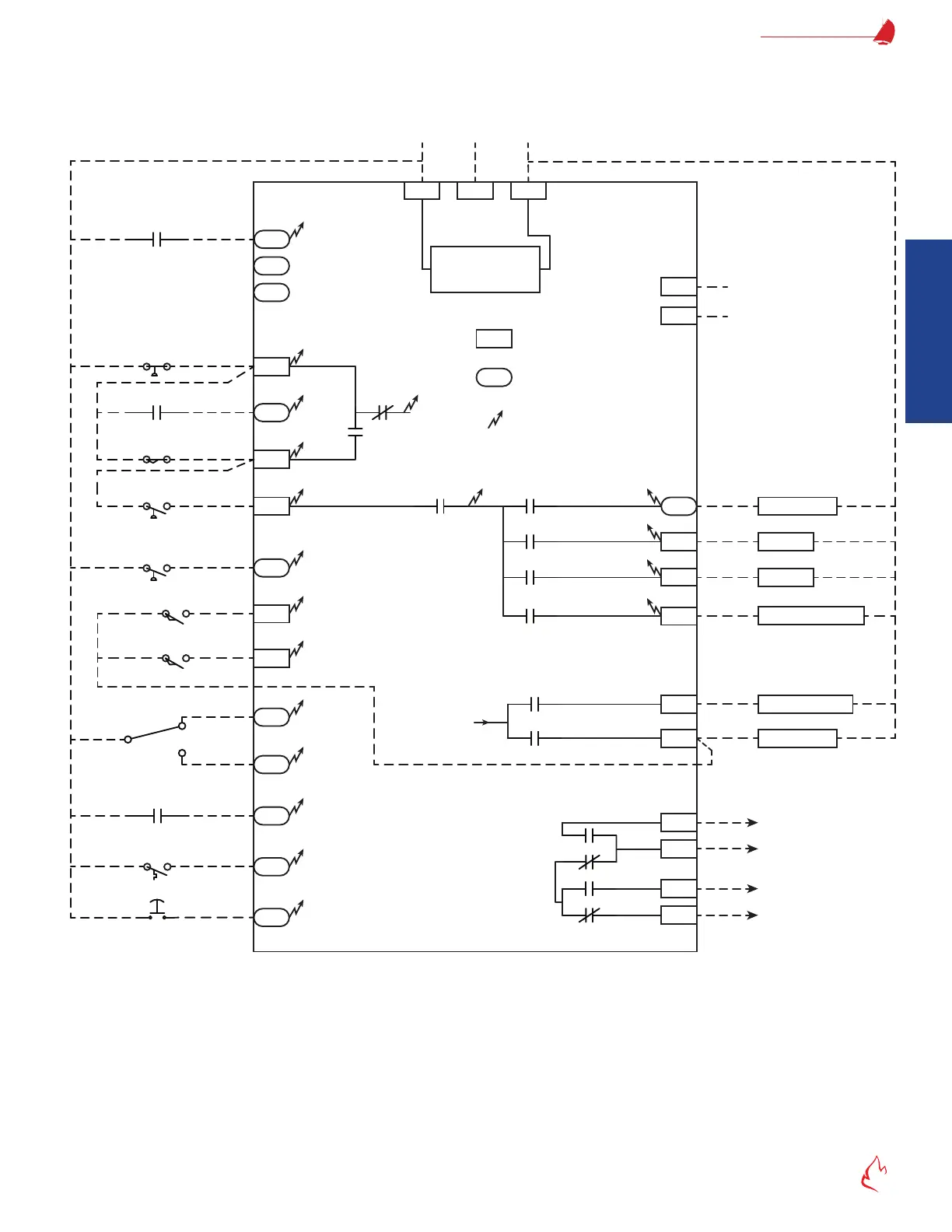
Figure 2 – 1 FF-11
L1
L1
G
G
L2
N
120 VAC
Fl+
Fl-
S1
S2
W
5
6
7
A
M
X
10
11
12
13
17
P
3
16
24
25
26
27
28
K8
K9
Purge Relay
Modulate Relay
Xfmr Relay
10s Pilot Relay
15s Pilot (MV2) Relay
SSOV (MV1) Relay
Lockout Alarm Relay
FD Start Relay
Safety Power Bus
K2
K3
K4
K5
K6
K7
Safety Relay
K1
+24V Output
4-20mA Input
}
External Flame
Intensity
High Fire (Purge)
Common
Modulate
Low Fire (Ignition)
}
Future (do not connect)
Remote Reset
Internal Diagram
Start
Limits
CFH Option
Running
Interlocks
Pre-Ignition Proof of
Valve Closure (POVC)
Valve Proving
Pressure Switch
Fuel Select
D
8
Low Fire (Ignition)
High Fire (Purge)
FD Fan Mode
LFH or DHW CFH Option
Ignition Xfmr
10 sPilot
15s Pilot*
Main Fuel Valve(s)
Lockout (Alarm)
Fan (Blower)
BMS
(Flame Safeguard)
Electronics
*(or MV2 if valve proving is used)
FR
Flame Relay
120V = Fixed Speed; 0V = VSD
Fuel 1
Fuel 2
K10
POC Bypass Relay
L1
= Tab connection to
existing wiring base
= pluggable terminal block on
the upper level of the BMS
= connection to BMS
internal electronics
0 BMS Internal Block Diagram