Installation – Servo Installation 2-25
FlexFit – Linkageless Control – Revision 1.0
PREFERRED
UTILITIES MFG CORPORATION
II
NN
SS
TT
AA
LL
LL
AA
TT
II
OO
NN
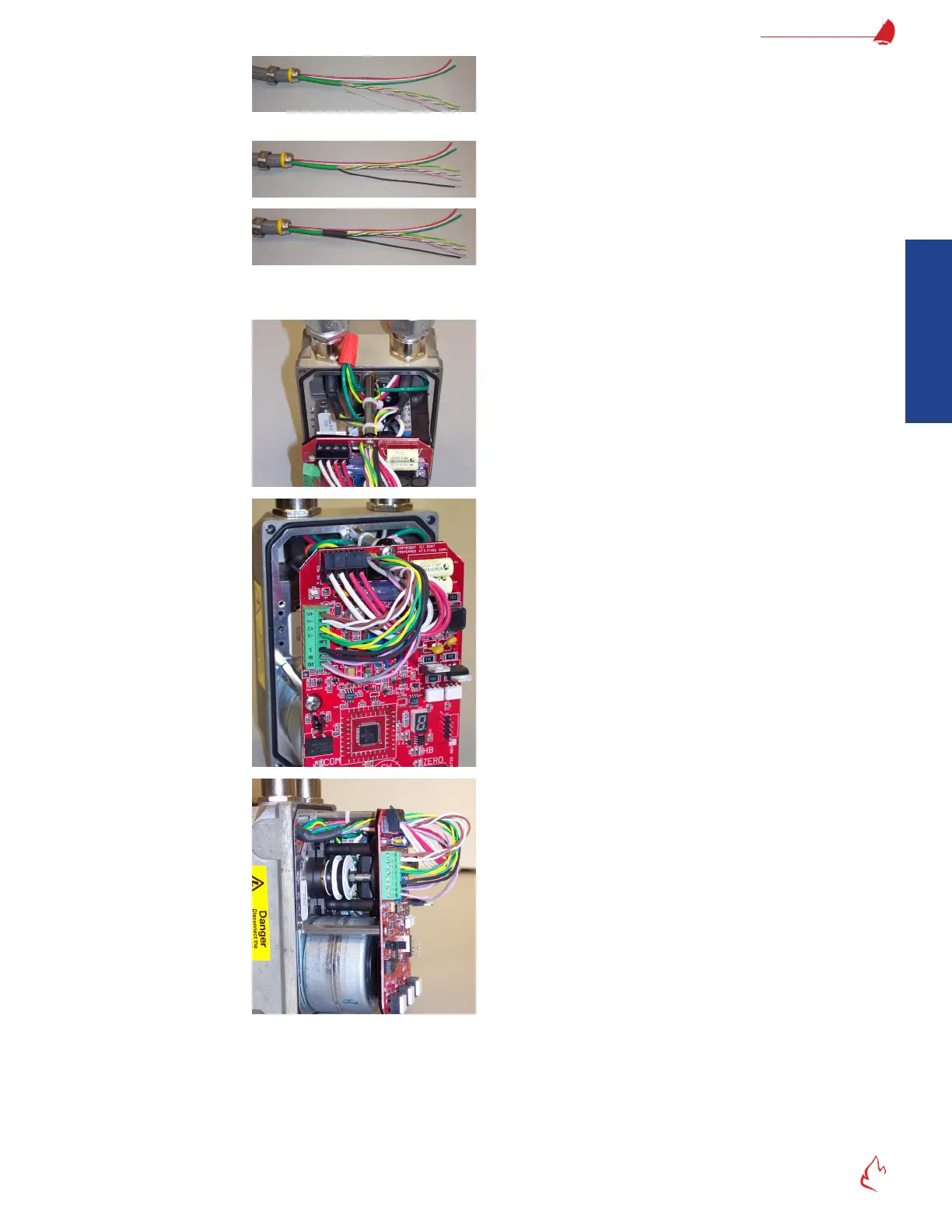
Separate the bare drain wire. Mark the pink/gray wire pair "IN" if it's coming for the
FlexFit or a previous servo. Mark the pink/gray wire pair "OUT" if it's going to the next servo in the daisy chain.
Slide the small insulator tubing over the drain wire and heat-shrink it.
Slide the large insulator tubing over the exposed shield braid and heat-shrink it.
All shielded cable braid, foil, and bare drain wire must be insulated. If any of these touches the conduit, servo metal, ground, or
any other exposed wires; electrical noise will be increased.
After preparing the shielded cable ends, pull the shielded
cables and the 120 VAC wires into the servo, and connect the
ex conduit to the servo.
Use wire ties to route the wires as shown. Keep the wires on
the back side of the stand-off to provide clearance for the cover.
Keep the wires away from the white limit switch cam adjustment
wheels.
Wire-nut the eld wiring ground wires to the green/yellow
servo ground wire.
Connect wires as described below. Be sure to prevent stray
strand shorts and ensure good connections.
Horizontal AC terminal strip:
Left two terminals: Neutral
Right two terminals: 120 VAC Hot
(terminal pairs are connected internally)
Vertical DC shielded cable terminal strip:
V+ Brown (+ 24 VDC)
V- White (24 VDC Common)
C+ Yellow (Communications +)
C- Green (Communications -)
Blank not used
S Shield drain wire (Heat shrink covered)
IN pink/gray pair (from the FlexFit or previous servo)
OUT Pink/gray pair (to the next servo in the daisy chain)
Very rmly tighten all terminal block screws. Tug on each
individual wire in each terminal to ensure that there is a good
connection.