Chapter 1 Introduction
1-3
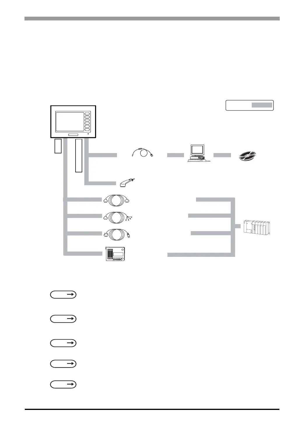
1.2 System Design
1.2.1 ST Series System Design
The following diagram represents the standard items connected to the ST Series unit.
ST RUN Mode Peripherals
ST400-AG41-24V
*1 This feature can only be used with Mitsubishi A, QnA and FX Series PLCs. For a list of compatible
units,
*2 For a list of compatible software,
*3 For recommended units,
*4 Certain types and models of PLCs cannot be connected.
*5 For details about connecting,
SEE
GP-PRO/PBIII for Windows Device/PLC Connection Manual (included with the screen editor
software)
SEE
GP-PRO/PBIII for Windows Device/PLC Connection Manual (included with the screen editor
software)
SEE
Recommended Units (Page 1-8)
SEE
GP-PRO/PBIII for Windows Operation Manual (included with the screen editor software)
SEE
GP-PRO/PBIII for Windows Device/PLC Connection Manual (included with the screen editor
software)
RUN Mode
ST Unit
Data Transfer Cable
GPW-CB02
GPW-CB03
Personal
Computer
Mitsubishi GPP
Software*
2
Bar-Code Reader*
3
(Limited to tested models)
RS-422 Cable
CA3-CBL422/5M-01
*
4
Host Controller
PLC etc.
Mitsubishi PLC FX Series
Connection Cable
CA3-CBLFX/1M-01
CA3-CBLFX/5M-01
When using the Internal 2-Port feature*
1
Mitsubishi PLC
A, QnA FX Series
2-Port Adaptor II
GP070-MD11
*5
F1
F2
F3
F4
F5
F6
Tool Connector
X Port
Mitsubishi A Connection Cable
CA3-CBLA-01
 Loading...