Chapter 3 Installation and Wiring
3-9
3.2.2 Connecting the Power Supply
Notes when the power supply is supplied. Please connect the power cable with the power supply connector on
the main body side with a power plug of the attachment.
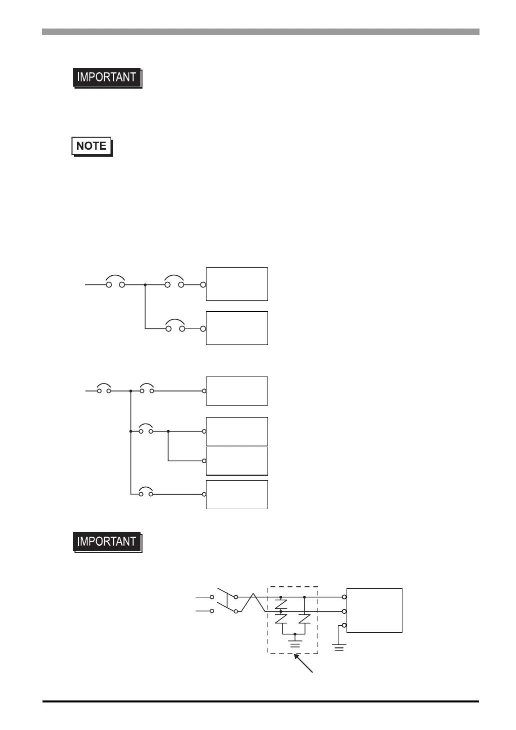
• When supplying power to the ST unit, please
separate the input/output and operation unit
lines, as shown.
• To increase the noise resistance quality of the
power cord, simply twist each power wire
before attaching the Ring Terminal.
• The power supply cord must not be bundled or
positioned close to main circuit lines (high volt-
age, high current), or input/output signal lines.
• Connect a lightning surge absorber, as shown in
the diagram, to deal with power surges.
•To avoid excess noise, make the power cord as
short as possible.
• Use flat screwriver (SIZE 0.6 x 3.5) to tighten the terminal block wire set screws.
The torque required to tighten these screws is 0.5 to 0.6 Nïm.
• Do not solder the wire itself.
• The power supply cord should be equivalent to the specification shown above. Be sure to twist
the power cords together, up to the power plug. (See illustration as shown below)
• The power supply plug MSTB2,5/3-ST-5,08 is made by Phoenix Contact.
• Be sure to ground the surge absorber (E1) separately from the ST unit (E2).
• Select a surge absorber that has a maximum circuit voltage greater than that of
the peak voltage of the power supply.
Main Power
Main
Power
ST Power
ST Power
Main Circuit
ST Unit
ST Unit
Input/Outpt
Unit
Input/Outpt
Power
Input/Outpt
Power
Power
Input/Outpt
Power
Input/Outpt
Operation
Unit
Motor
ST Unit
FG
E2
E1
Lightning Surge Absorber