ST Series User’s Manual
2-10
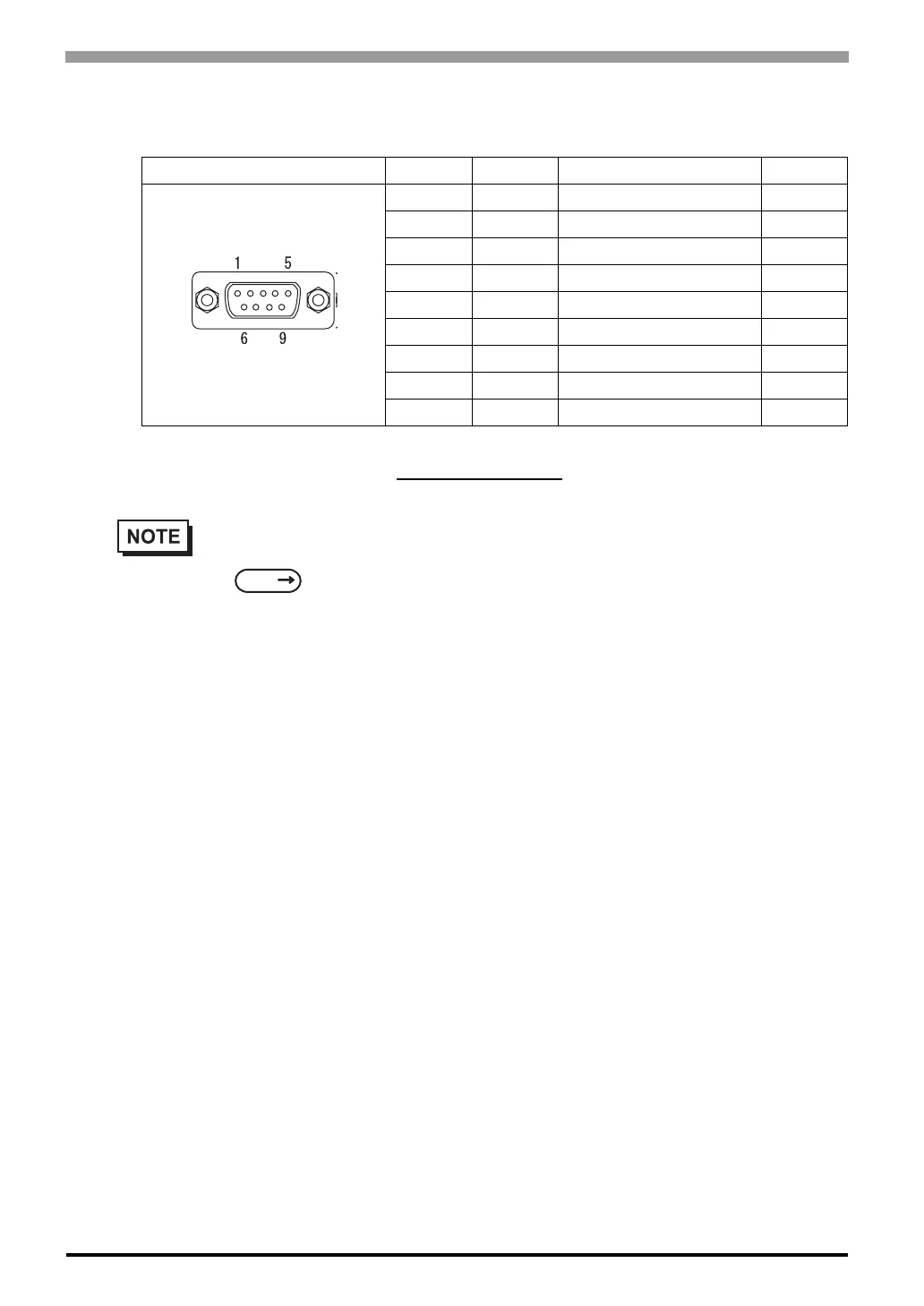
Expansion Serial Interface
RS-422 Interface (Y)
Recommended Connector : Dsub 9 pin socket-type XM2D-0901 <made by OMRON Corp.>
Recommended Cover : Dsub 9 pin cover XM2S-0913 <made by OMRON Corp.>
Pin Connection Pin No. Signal Signal Name Direction
*1
*1 The connector of the ST side is pin type.
1 RDA Receive data A Input
2 RDB Receive data B Input
3 SDA Send data A Output
4 ERA Enable receive A Output
5 SG Ground -
6 CSB Clear send B Input
7 SDB Send data B Output
8 CSA Clear send A Input
9 ERB Enable receive B Output
• This communication port is used exclusively for Extended SIO Scripts. To use this port, an
Extended SIO Script is required.
GP-PRO/PBIII for Windows Device/PLC Connection Manual (included with the
screen editor software)
• Use inch type screw (#4-40UNC) as set screws.
• The following pairs of pin #’s must be connected to each other.
#6(CSB) <-> #9(ERB)
#8(CSA) <-> #4(ERA)
• This unit is not equipped internally with termination resistance. Attach termination resistance to
the cable. If there is no designation on the PLC/Device side, attach 100Ω1/2W.
SEE