Chapter 2 Specifications
2-11
2.3.4 ST403-AG41-24V
Ethernet Interface
(X)
This is the Ethernet Interface of 10 BASE-T. LED lights up or blinks according to the status.
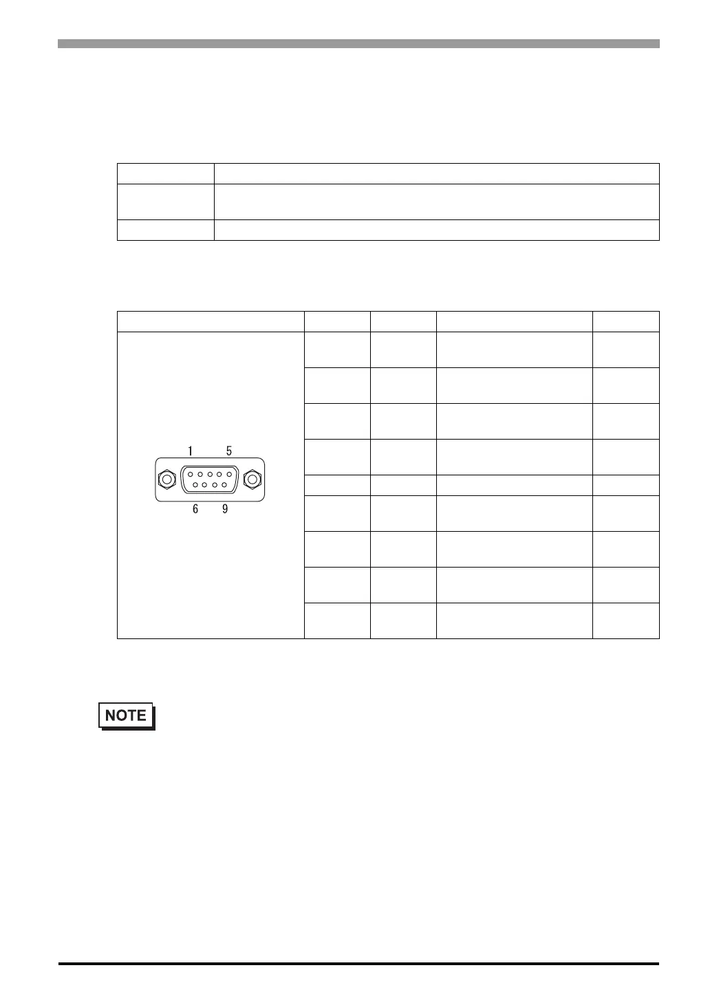
Serial Interface
RS-232C/RS-422 Interface (Y)
*1
Recommended Connector : Dsub 9 pin socket-type XM2D-0901 <made by OMRON Corp.>
Recommended Cover : Dsub 9 pin cover XM2S-0913 <made by OMRON Corp.>
LED Contents
Orange
When the power supply is on, LED lights up.
When sending or receiving, LED blinks.
Green When linking, LED lights up.
Pin Connection Pin No. Signal Signal Name Direction
1 CD/RDA
Carrier detect
/Receive data A
Input
/Inpu
2 RD/RDB
Receive data
/Receive data B
Input
/Input
3 SD/SDA Send data/Send data A
Output
/Output
4ER/ERA
Enable receive
/Enable receive A
Output
/Output
5 SG/SG Ground/Ground -
6 DR/CSB
Data set ready/Clear
send B
Input
/Input
7RS/SDB
Request send
/Send data B
Output
/Output
8 CS/CSA Clear send/Clear send A
Input
/Input
9RI/ERB
Ring indicate
/Enable receive B
Input
/Output
*1 Transmission method is used by changing in the screen editor software or in the setting at the ST unit.
• Use inch type screw (#4-40UNC) as set screws.
• RS-422 is not equipped internally with termination resistance. Attach termination resistance to
the cable.