ST Series User’s Manual
2-8
2.3 Interface Specifications
2.3.1 ST400-AG41-24V
Serial Interface
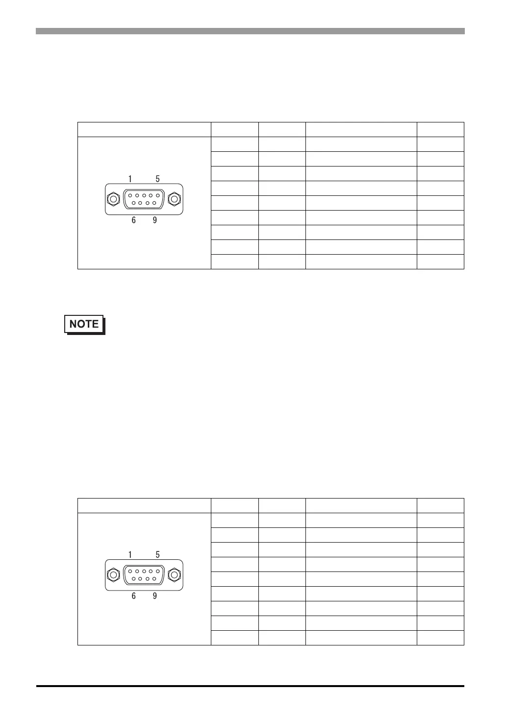
RS-422 Interface (X)
Recommended Connector : Dsub 9 pin socket-type XM2D-0901 <made by OMRON Corp.>
Recommended Cover : Dsub 9 pin cover XM2S-0913 <made by OMRON Corp.>
2.3.2 ST401-AG41-24V
Serial Interface
RS-232C Interface (Y)
Recommended Connector : Dsub 9 pin socket-type XM2D-0901 <made by OMRON Corp.>
Recommended Cover : Dsub 9 pin cover XM2S-0913 <made by OMRON Corp.>
Pin Connection Pin No. Signal Signal Name Direction
1 RDA Receive data A Input
2 RDB Receive data B Input
3 SDA Send data A Output
4 ERA Enable receive A Output
5 SG Ground -
6 CSB Clear send B Input
7 SDB Send data B Output
8 CSA Clear send A Input
9 ERB Enable receive B Output
• RS-422 (4-wire or 2-wire) can be used to connect the ST with Devices/PLCs.
• Use inch type screw (#4-40UNC) as set screws.
• The following pairs of pin #’s must be connected to each other.
#6(CSB) <-> #9(ERB)
#8(CSA) <-> #4(ERA)
• This unit is not equipped internally with termination resistance. Attach termination resistance to
the cable. If there is no designation on the PLC/Device side, attach 100Ω1/2W.
Pin Connection Pin No. Signal Signal Name Direction
1 CD Carrier detect Input
2 RD Receive data Input
3 SD Send data Output
4 ER Enable receive Output
5 SG Ground -
6 DR Data set ready Input
7 RS Request send Output
8 CS Clear send Input
9 RI Ring indicate Input