PLX32-EIP-MBTCP-UA ♦ Multi-Protocol Gateway EIP Protocol
User Manual
ProSoft Technology, Inc. Page 51 of 156
March 8, 2018
Adding the Gateway to RSLogix5000 v.16 through v.19
Note: Class 1 connections are not supported in RSLogix v.15 and older
1 Start Rockwell Automation RSLogix 5000.
2 In the Controller Organizer, right-click the EtherNet/IP bridge in the I/O tree
and choose NEW MODULE.
3 In the Select Module Type dialog box, click FIND. Search for Generic
EtherNet Bridge, click Generic Ethernet Bridge, and then click CREATE.
4 In the New Module dialog box, enter a name for the gateway, then enter the
IP address of the PLX32-EIP-MBTCP-UA. This creates the communication
path from the processor to the PLX32-EIP-MBTCP-UA.
5 Add a new module under the Generic EtherNet Bridge and add a CIP
Connection (CIP-MODULE). Here is where you specify the parameters for
the I/O connection. The input and output sizes need to match the input and
output sizes configured in PCB. The ADDRESS field value represents the
connection number in PCB. By default all of the connections have 248 Input
words, 248 Output words, and 0 Configuration words. Set the Comm format
to Data type INT, and set the Assembly instances to be "1" for input, "2" for
output, and "4" for configuration.
6 Add and configure a CIP Connection for each I/O connection.
Configuring EIP Class 1 Connections in PCB
After you have created the PLX32-EIP-MBTCP-UA gateway in RSLogix 5000,
you must configure the connections in the module.
To configure Class 1 connections in PCB
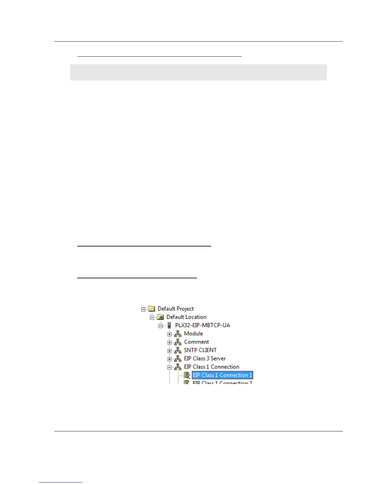
1 In ProSoft Configuration Builder, click the [+] next to the gateway, then click
the [+] next to EIP Class 1 Connection [x].
2 Double-click the EIP Class 1 Connection [x] to display the Edit - EIP Class 1
Connection [x] dialog box.