ULTRA 4 INSTRUCTION MANUAL
32
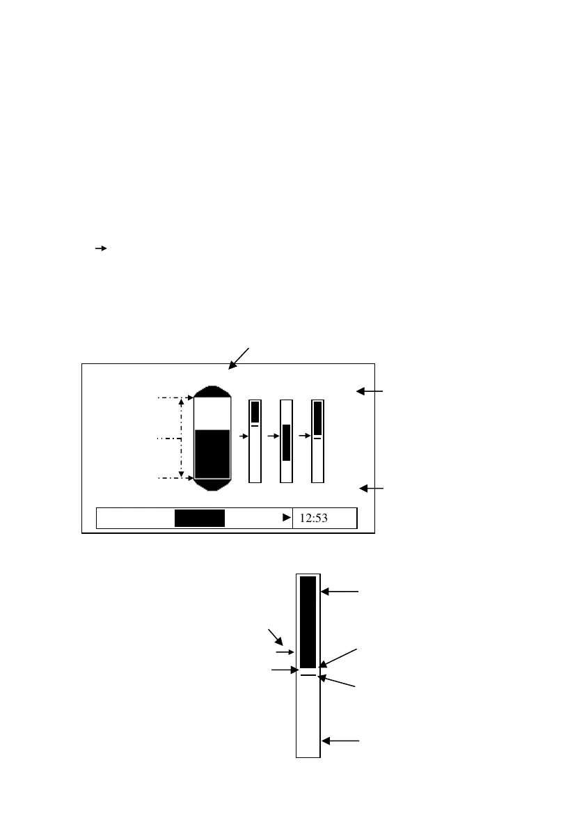
Settings Display
The Settings screen displays the transducer settings and has a bar-graph
showing the measured value or as a percentage of maximum. To the left of
the display:
• P105 = Empty Level
• P106 = Span
• P107 = Near Blanking.
Also, on this screen are indicators of any relays currently setup. The level
icons represent the level reading of the transducer. Relays that do not
relate to the level (Miscellaneous) will be displayed without the graphical
representation of setpoints but will however show the relay number and
status. Below is an example of information on the Settings screen:
Region between solid area and
line signifies a relay can be
ACTIVE if triggered, or
INACTIVE if not triggered.

 Loading...


