HandKey II Installation and Operation Manual
Page 24 Revision 2.0
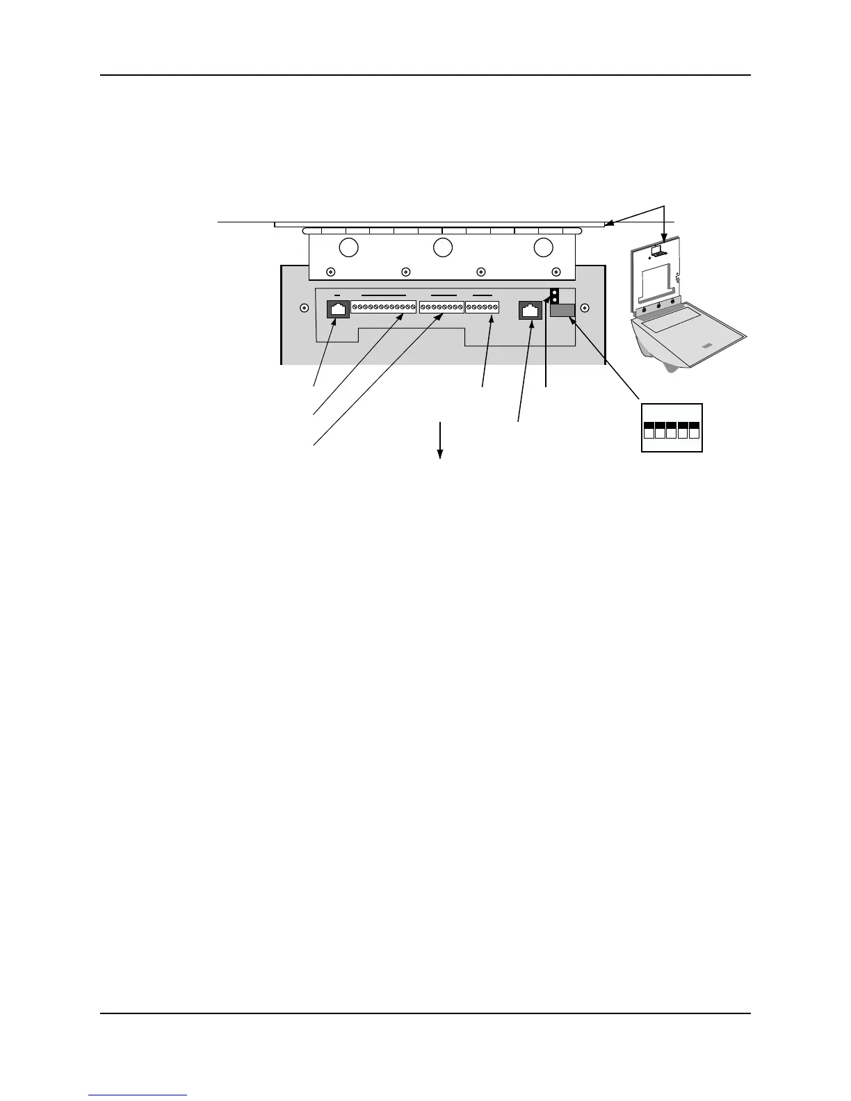
Wiring Connections
Once the Hand Reader is attached to the wall plate the wiring connections to the Hand
Reader can be made (see Figure 3-3).
Figure 3-3: Wiring Connections and Dip Switches
Wiring Examples
The following Tables provide the pin outs for the terminal strips on the Hand Reader.
• Table 2 on page 25 provides the pin outs for TS-1: Power and Communication
Connections.
• Table 3 on page 25 provides the pin outs for TS-2: Input Connections.
• Table 4 on page 26 provides the pin outs for TS-3: Card Reader and Output
Connections.
The following Figures provide typical Hand Reader wiring digrams.
• Figure 3-4 on provides a typical Lock Output wiring diagram.
• Figure 3-5 on provides a typical Auxiliary Output wiring diagram.
• Figure 3-6 on provides a typical Card Reader Emulation Mode wiring diagram.
• Figure 3-7 on provides a typical RS-485 4-Wire Master/Remote Network System
wiring diagram.
• Figure 3-8 on provides a typical RS-422 2-Wire Master/Remote Network System
wiring diagram.
• Figure 3-9 on provides a typical Host PC Network System wiring diagram.
• Figure 3-10 on provides a typical Printer to Hand Reader wiring diagram.
WALL
ON
OFF
5 4 3 2 1
RS-232 RJ-45
TS-3 Terminals 26 to 15
TS-2 Terminals 14 to 7
TS-1 Terminals 6 to 1
Optional Modem
or Ethernet Jack
Dip Switches
Wall Plate
Top of
Terminal
Top of Hand Reader
14
76 11526
Backup Battery
Jumper
81