RDL-3000 User Manual
70-00158-01-DRAFT Proprietary Redline Communications © 2010 Page 44 of 142 November 25, 2010
4.3 Dashboard Display
4.3.1 General Information
The dashboard is displayed at the top of all screens. This feature displays a summary of
important operational information including the unit IP address, operating frequency,
time, wireless and Ethernet status, and the radio temperature.
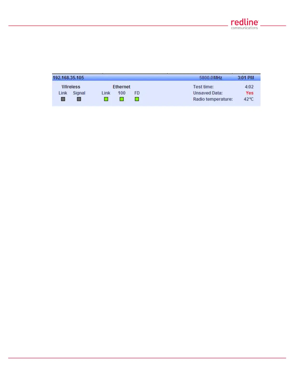
Fig. 27: Web - Dashboard Display
IP Address: IP address of this unit.
Wireless Frequency: RF frequency in use.
Time: Current time obtained from Web browser.
Test time: Visible only when the Test function is active. The last saved configuration is
restored when counter reaches zero (no reboot).
Unsaved Data: Indicates if the running configuration matches the saved configuration.
No: There are no differences between the running and saved configurations.
Yes: There are differences between the running and saved configurations. The current
settings are discarded at the next system rebooted or when the saved configuration is
restored through use of the Test function. Click Save All in the main menu to save the
current running configuration. This configuration will be restored on power-up, reboot, or
the end of a test cycle.
Saving: The system is saving the runtime parameters to non-volatile RAM.
Radio Temperature: Internal temperature of the radio.
4.3.2 Wireless Leds
These LED indicators provide a summary of the wireless status.
Link LED
The wireless Link LED lights solid green under the following conditions:
Sector Controller: Wireless link is established to one or more subscribers.
Subscriber: Wireless link is established to the sector controller.
Signal LED
The wireless Signal LED operation is based on the Adaptive Modulation and Uncoded
Burst Rate (UBR) settings for each subscriber. These fields are on the Subscriber Link
Configuration screen.
Adaptive Modulation Enabled: LED lights solid green when the wireless link is
operating at the rate equal to the UBR setting for this link. The LED blinks when the link
is operating at a rate lower than the UBR setting.
Adaptive Modulation Disabled: LED lights solid green when the wireless link is
established.
4.3.3 Ethernet LEDs
These LED indicators provide a summary of the Ethernet port status.