RL78/F13, F14 CHAPTER 23 STANDBY FUNCTION
R01UH0368EJ0210 Rev.2.10 1531
Dec 10, 2015
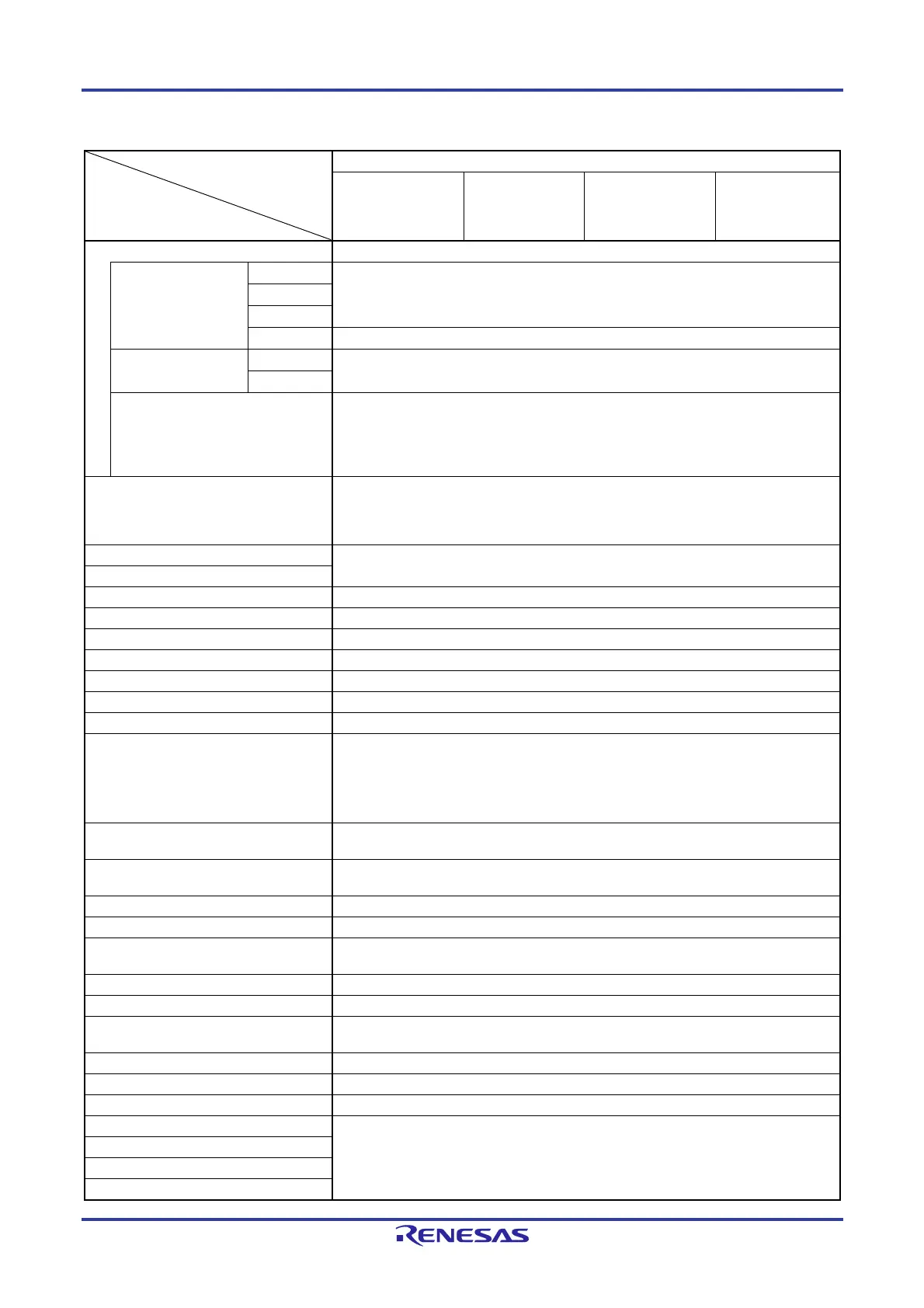
Table 23-2. Operating Statuses in STOP Mode
STOP Mode Setting
Item
When STOP Instruction Is Executed While CPU Is Operating on Main System Clock
When CPU Is
Operating on High-
speed On-chip
Oscillator clock (f
IH)
When CPU Is
Operating on X1
Clock (f
X)
When CPU Is
Operating on
External Main
System Clock (f
EX)
When CPU Is
Operating on PLL
Clock (f
PLL)
System clock Clock supply to the CPU is stopped
Main system clock f
IH Stopped
f
X
f
EX
f
PLL Operation disabled
Subsystem clock f
XT Status before STOP mode was set is retained
f
EXS
f
IL Set by bit 0 (SELLOSC) of the CKSEL register and bit 4 (WUTMMCK0) of the OSMC
register.
WUTMMCK0 = 1: Oscillates
WUTMMCK0 = 0 and SELLOSC = 1: Oscillates
WUTMMCK0 = 0 and SELLOSC = 0: Stops
fWDT Set by bits 0 (WDSTBYON) and 4 (WDTON) of user option byte (000C0H/020C0H)
WDTON = 0: Stops
WDTON = 1 and WDSTBYON = 1: Oscillates
WDTON = 1 and WDSTBYON = 0: Stops
CPU Operation stopped
Code flash memory
Data flash memory Operation stopped (the STOP instruction is not executed during data flash programming)
RAM Operation stopped
Port (latch) Status before STOP mode was set is retained
Timer array unit Operation disabled
Real-time clock (RTC) Operable (when the subsystem clock is selected as an input clock (fRTC))
Watchdog timer See CHAPTER 11 WATCHDOG TIMER
Clock monitor Operation stopped
Timer RJ Operable
In the event counting mode when no TRJIO0 input filters are selected.
If the subsystem/low-speed on-chip oscillator select clock is selected as the clock
source for counting and the RTCLPC bit of the OSMC register is 0.
If the low-speed on-chip oscillator is selected as the clock source for counting.
Timer RD Operable (can only operate for output of the SNOOZE status signal when the
subsystem/low-speed on-chip oscillator select clock is selected)
Clock output/buzzer output Operable only when the subsystem/low-speed on-chip oscillator select clock is selected
as the count clock
A/D converter Wakeup operation is enabled (switching to the SNOOZE mode)
D/A converter Operable (the state before the STOP mode was set is retained)
Comparator Operable (if the settings allow release from the STOP mode and the digital filters are not
in use)
Serial array unit (SAU) Operation disabled
Serial interface (IICA) Wakeup operation by address match is enabled
DTC Reception of trigger signals from sources for DTC activation is enabled (switching to the
SNOOZE mode)
ELC Linking between operational function blocks is possible.
LIN/UART module (RLIN3) Only wakeup operation of the UART is possible (switching to the SNOOZE mode).
CAN interface (RS-CAN lite) Operation disabled
Power-on-reset function Operable
Voltage detection function
External interrupt
Key interrupt function
 Loading...


