RL78/F13, F14 CHAPTER 30 FLASH MEMORY
R01UH0368EJ0210 Rev.2.10 1640
Dec 10, 2015
30.6.2 Boot swap function
If rewriting the boot area failed by temporary power failure or other reasons, restarting a program by resetting or
overwriting is disabled due to data destruction in the boot area.
The boot swap function is used to avoid this problem.
Before erasing boot cluster 0
Note
, which is a boot program area, by self-programming, write a new boot program to boot
cluster 1 in advance. When the program has been correctly written to boot cluster 1, swap this boot cluster 1 and boot cluster
0 by using the set information function of the firmware of the RL78/F13 or RL78/F14, so that boot cluster 1 is used as a boot
area. After that, erase or write the original area, boot cluster 0.
As a result, even if a power failure occurs while the area is being rewritten, the program is executed correctly because it
is booted from boot cluster 1 to be swapped when the program is reset and started next.
Note A boot cluster is an 8 KB area and boot clusters 0 and 1 are swapped by the boot swap function.
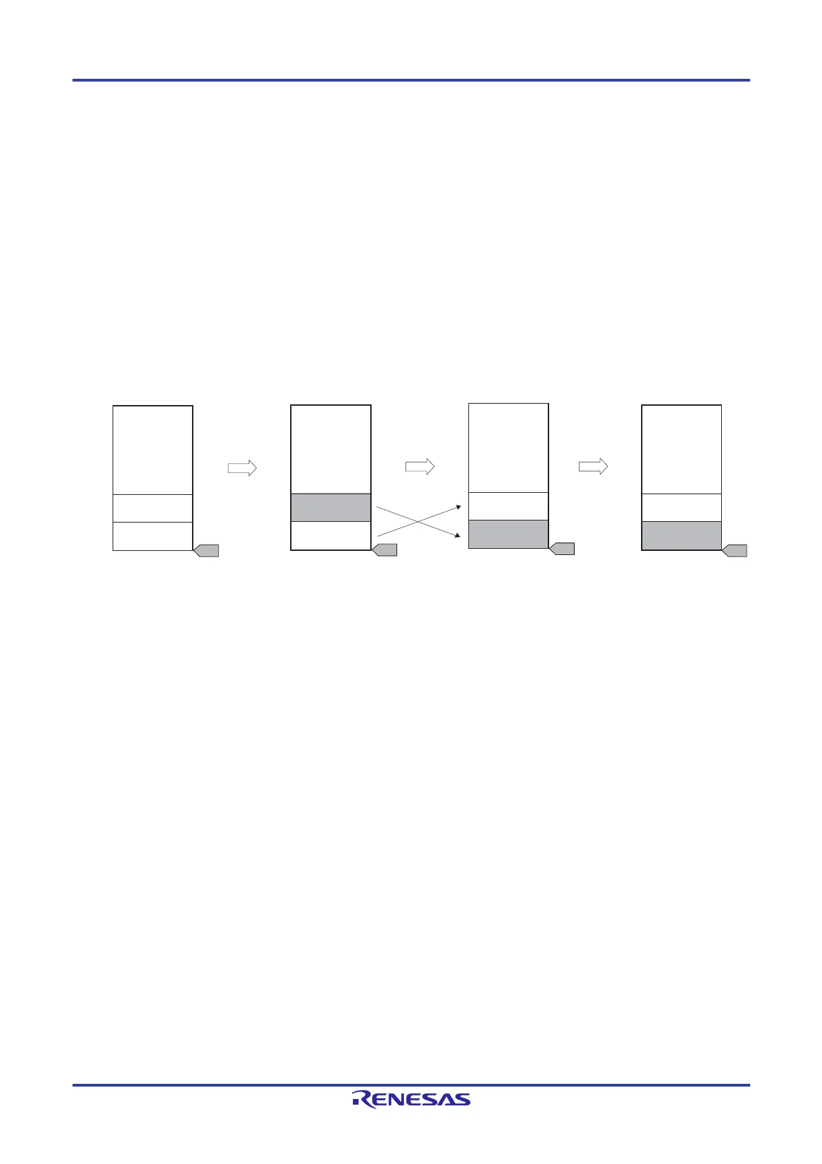
Figure 30-9. Boot Swap Function
In an example of above figure, it is as follows.
Boot cluster 0: Boot program area before boot swap
Boot cluster 1: Boot program area after boot swap
Boot program
(boot cluster 0)
New boot program
(boot cluster 1)
User program
Self-programming
to boot cluster 1
Self-programming
to boot cluster 0
Execution of boot
swap by firmware
User program
Boot program
(boot cluster 0)
User program
New user program
(boot cluster 0)
New boot program
(boot cluster 1)
User program
New boot program
(boot cluster 1)
Boot program
(boot cluster 0)
User program
XXXXXH
04000H
00000H
02000H
Boot
Boot
Boot
Boot
 Loading...


