RL78/F13, F14 CHAPTER 15 SERIAL ARRAY UNIT
R01UH0368EJ0210 Rev.2.10 824
Dec 10, 2015
15.3.17 Port input mode registers 1, 3, 5 to 7, 12 (PIM1, PIM3, PIM5 to PIM7, PIM12)
These registers set the input buffer of ports 1, 3, 5 to 7, and 12 in 1-bit units.
Set the PIM1, PIM3, PIM5 to PIM7, and PIM12 registers by a 1-bit or 8-bit memory manipulation instruction.
Reset signal generation clears the PIM1, PIM3, PIM5 to PIM7, and PIM12 registers to 00H.
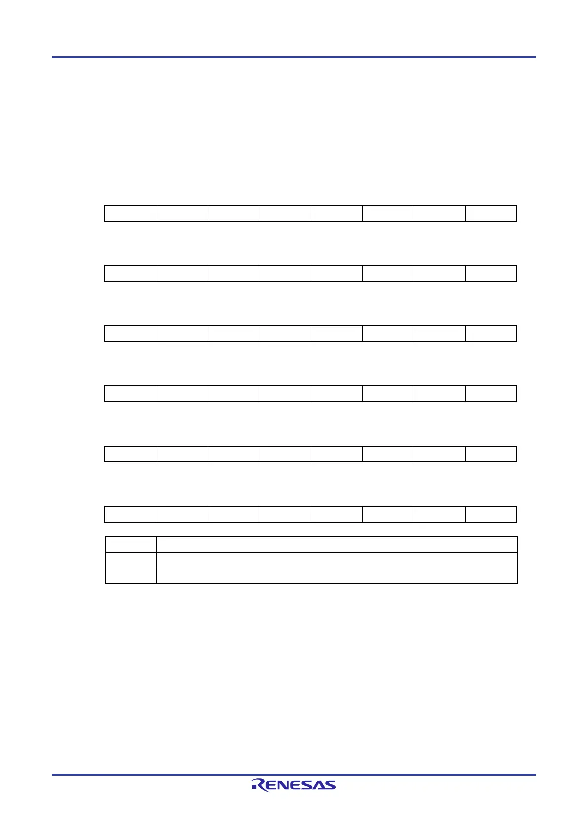
Figure 15-20. Format of Port Input Mode Registers 1, 3, 5 to 7, and 12 (PIM1, PIM3, PIM5 to PIM7, PIM12)
Address F0041H After reset: 00H R/W
Symbol 7 6 5 4 3 2 1 0
PIM1 PIM17 PIM16 0 PIM14 PIM13 0 PIM11 PIM10
Address F0043H After reset: 00H R/W
Symbol 7 6 5 4 3 2 1 0
PIM3 0 0 0 0 0 0 0 PIM30
Address F0045H After reset: 00H R/W
Symbol 7 6 5 4 3 2 1 0
PIM5 0 0 0 PIM54 0 0 0 0
Address F0046H After reset: 00H R/W
Symbol 7 6 5 4 3 2 1 0
PIM6 0 0 0 0 PIM63 PIM62 0 0
Address F0047H After reset: 00H R/W
Symbol 7 6 5 4 3 2 1 0
PIM7 0 0 0 0 PIM73 0 PIM71 PIM70
Address F004CH After reset: 00H R/W
Symbol 7 6 5 4 3 2 1 0
PIM12 0 0 PIM125 0 0 0 0 0
PIMmn Pmn pin input buffer selection (m = 1, 3, 5 to 7, 12; n = 0, to 7)
0 Normal input buffer
1 TTL input buffer
 Loading...


