RL78/F13, F14 CHAPTER 5 CLOCK GENERATOR
R01UH0368EJ0210 Rev.2.10 413
Dec 10, 2015
5.6.7 Conditions before Changing CPU Clock and Processing after Changing CPU Clock
The following table shows the conditions before changing the CPU clock and the processing after changing the CPU
clock.
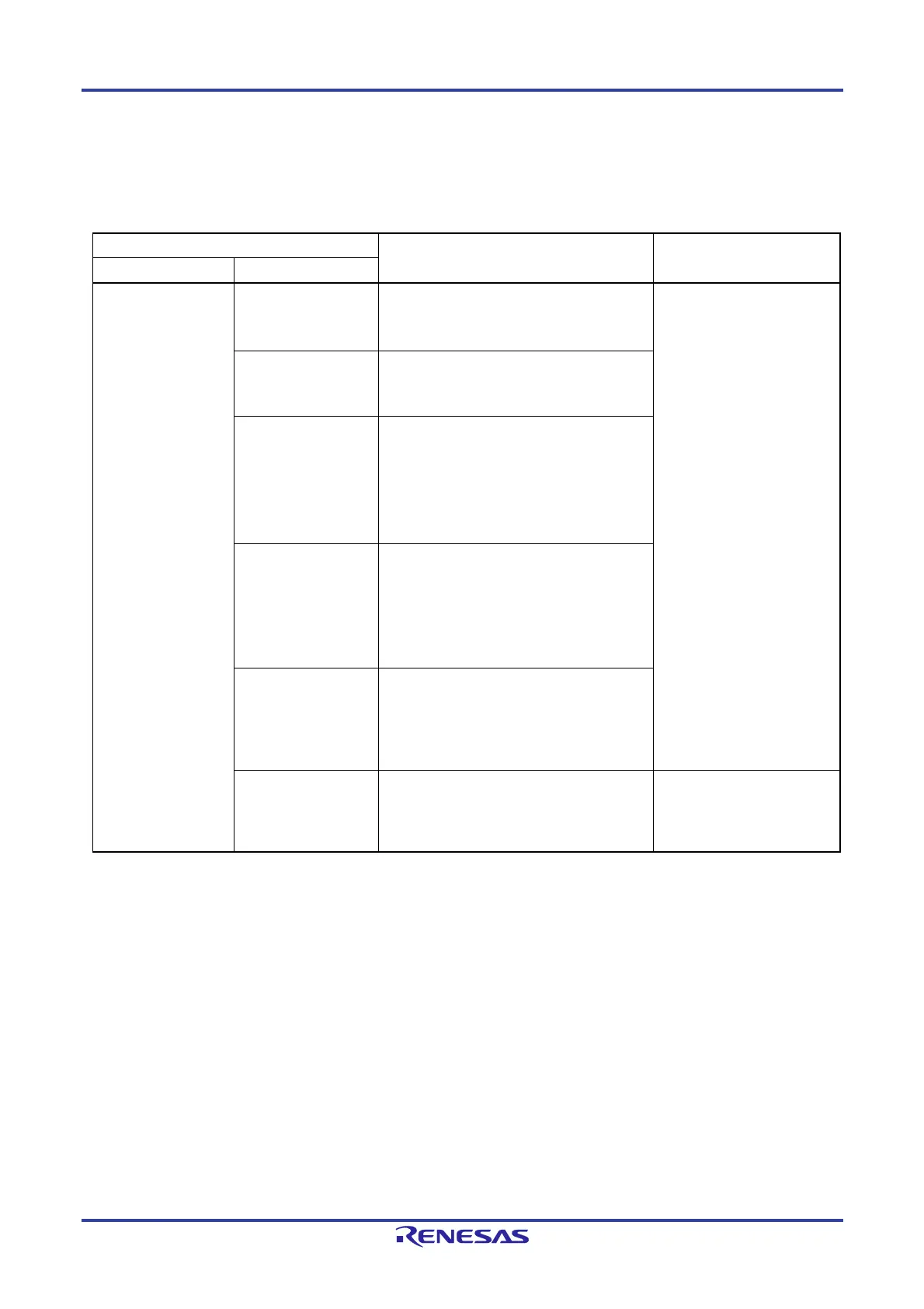
Table 5-3. Changing CPU Clock (1/7)
CPU Clock Conditions before Change Processing after Change
Before Change After Change
High-speed on-chip
oscillator clock
X1 clock X1 oscillation is stable.
OSCSEL = 1, EXCLK = 0, MSTOP = 0
After elapse of oscillation stabilization time
Stopping the high-speed on-
chip oscillator (HIOSTOP = 1)
can reduce the operating
current.
External main system
clock
External clock input from the EXCLK pin is
enabled.
OSCSEL = 1, EXCLK = 1, MSTOP = 0
XT1 clock
XT1 oscillation is stable, and the subsystem
clock is selected as the subsystem/low-speed
on-chip oscillator select clock.
OSCSELS = 1, EXCLKS = 0, XTSTOP = 0
SELLOSC = 0
After elapse of oscillation stabilization time
External subsystem
clock
External clock input from the EXCLKS pin is
enabled, and the subsystem clock is selected
as the subsystem/low-speed on-chip oscillator
select clock.
OSCSELS = 1, EXCLKS = 1, XTSTOP = 0
SELLOSC = 0
Low-speed on-chip
oscillator clock
The low-speed on-chip oscillator starts
oscillation, and the low-speed on-chip oscillator
clock is selected as the subsystem/low-speed
on-chip oscillator select clock.
OSCSELS = 1, SELLOSC = 1
PLL clock PLL oscillation is stable.
LOCK = 1, PLLON = 1
The high-speed on-chip
oscillator cannot be stopped
because it is the PLL input
clock.
Remark For details about the register flag settings for stopping the target clock during the processing after change and
conditions before the clock is stopped, see 5.6.9 Conditions Before Clock Oscillation Is Stopped.
 Loading...


